5 - 7
5 Designing the Power Supply System
NX-series EtherNet/IP Coupler Unit User’s Manual (W536)
5-2 Designing the NX Unit Power Supply System
5
5-2-2 Calculation Example for the NX Unit Power Supply
NX Unit Power Supply Capacity and Restrictions
The internal power supply circuits of the EtherNet/IP Coupler Unit or Additional NX Unit Power Sup-
ply Unit supply the NX Unit power to the NX Units.
The NX Unit power supply capacity does not include the NX Unit power consumption of the Ether-
Net/IP Coupler Unit or Additional NX Unit Power Supply Units.
The NX Unit power supply capacity of the EtherNet/IP Coupler Unit is restricted by the following
application conditions.
• Ambient operating temperature
• Installation orientation
Consider these conditions and determine the required NX Unit power supply capacity, and then
design the NX Unit power supply system.
Refer to 3-1-2 EtherNet/IP Coupler Unit Specifications on page 3-3 for restrictions on the Ether-
Net/IP Coupler Unit.
For restrictions on the Additional NX Unit Power Supply Unit, refer to the NX-series System Units
User’s Manual (Cat. No. W523).
Precautions for Correct Use
• Do not exceed the NX Unit power supply capacity. If you exceed the NX Unit power supply
capacity, malfunction may occur.
• Use the same Unit power supply to supply the Unit power to the entire Slave Terminal. If you
supply power from different Unit power supplies, differences in electrical potential may cause
unexpected currents in the NX Unit power supply, which may result in failure or malfunction.
This section provides a calculation example for the NX Unit power supply.
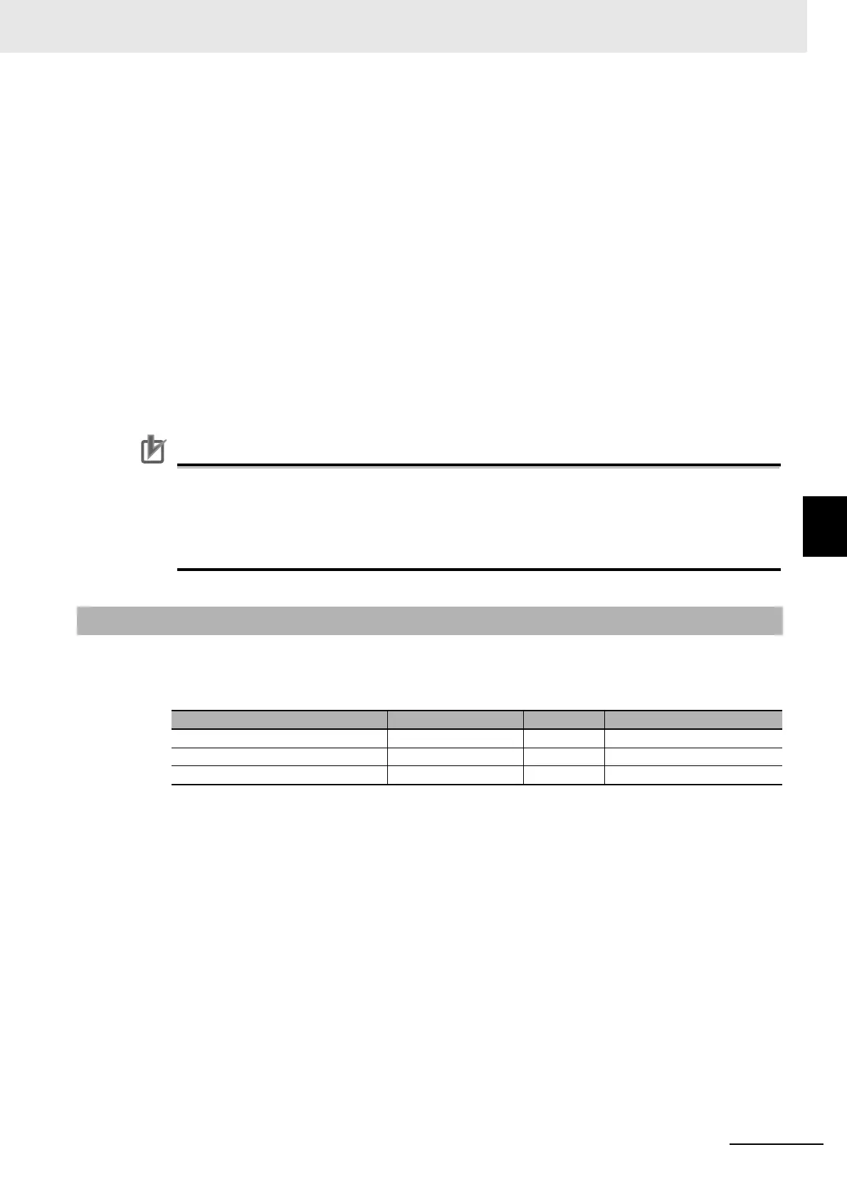
Unit Configuration Example
Application Conditions
The ambient operating temperature is 55°C and an upright installation orientation is used.
Calculating the Total Power Consumption from the NX Unit Power Supply
Calculate the total power consumption from the NX Unit power supply that is required by the NX
Units that are connected to the EtherNet/IP Coupler Unit. The NX Unit power consumption of the
EtherNet/IP Coupler Unit is not included in this calculation.
Total power consumption from NX Unit power supply [W] = (0.5 W × 5) + (0.8 W × 5) = 6.5 W
Confirming the NX Unit Power Supply Capacity of the EtherNet/IP Coupler
Unit
According to the graph in Installation orientation and restrictions on page 3-5 in 3-1-2 EtherNet/IP
Coupler Unit Specifications on page 3-3, the NX Unit power supply capacity is 8.5 W max. There-
fore, in this example, the total power consumption from the NX Unit power supply is 6.5 W, and the
NX Unit power supply capacity is 8.5 W max., so the design conditions are met.
5-2-2 Calculation Example for the NX Unit Power Supply
Name Model Quantity Power consumption/Unit
EtherNet/IP Coupler Unit NX-EIC202 1 1.60 W
Digital Input Unit NX-ID3317 5 0.5 W
Relay Output Unit NX-OC2633 5 0.8 W
 Loading...


