5 Designing the Power Supply System
5 - 2
NX-series EtherNet/IP Coupler Unit User’s Manual (W536)
5-1 Power Supply System and Design
Concepts
This section describes the power supply system for an EtherNet/IP Slave Terminal and the design con-
cepts.
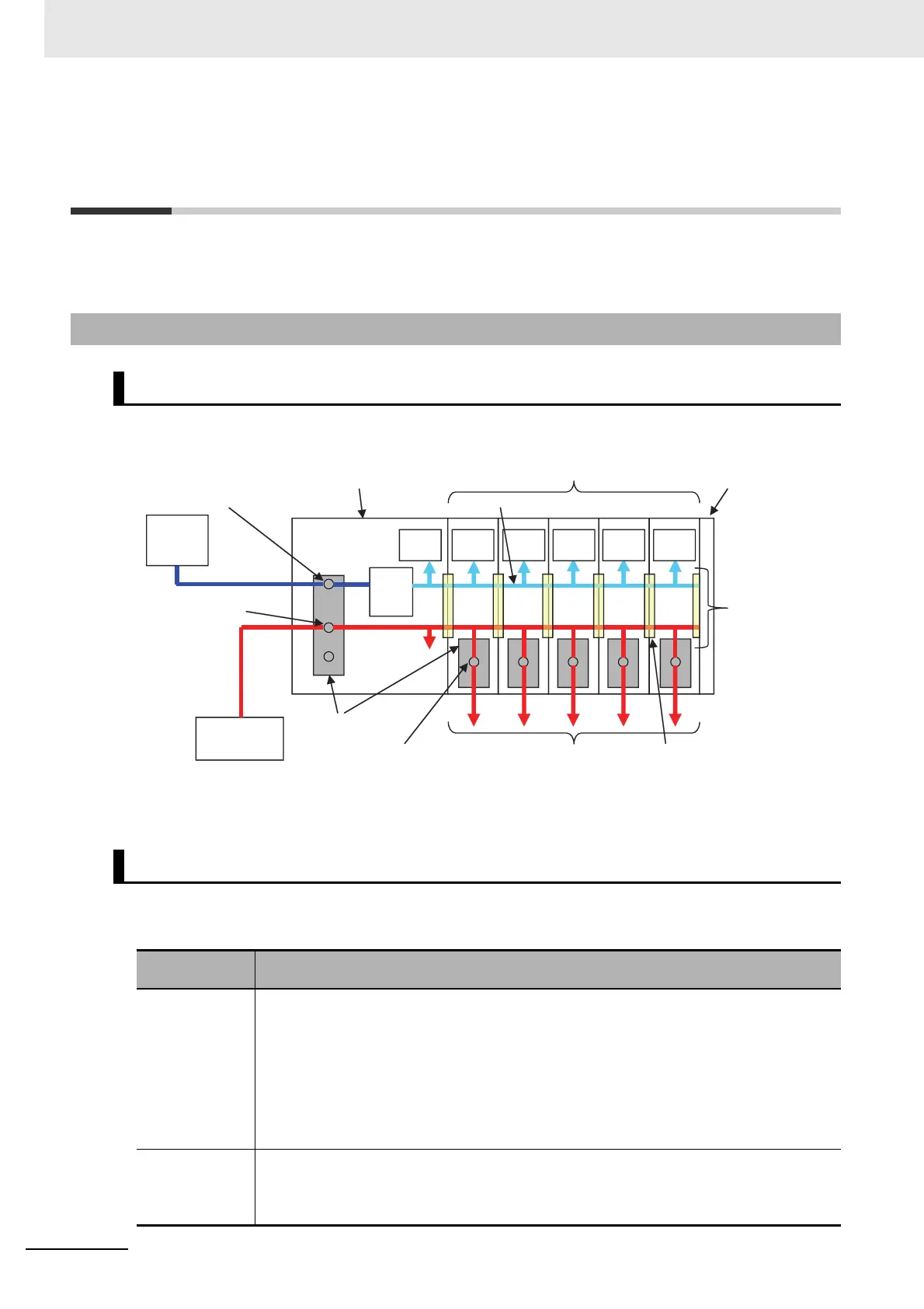
An example of a power supply system configuration diagram for an EtherNet/IP Slave Terminal is
shown below.
There are the following two types of power supplies that supply power to the EtherNet/IP Slave Termi-
nal.
5-1-1 Power Supply System and Types of Power Supplies
Power Supply System Configuration Diagram
Power Supply Types
Power supply
type
Description
Unit power sup-
ply
This power supply is required to generate the NX Unit power, which is necessary for the Eth-
erNet/IP Slave Terminal to operate. This power supply is connected to the Unit power supply
terminals on the EtherNet/IP Coupler Unit.
The internal power supply circuit in the EtherNet/IP Coupler Unit generates the NX Unit
power supply from the Unit power supply. The internal circuits of the EtherNet/IP Coupler Unit
and of the NX Units operate on the NX Unit power supply.
The NX Unit power is supplied to the NX Units in the Slave Terminal through the NX bus con-
nectors.
I/O power supply This power supply drives the internal I/O circuits of the NX Units and it is used for the con-
nected external devices. This power supply is connected to the I/O power supply terminals on
the EtherNet/IP Coupler Unit. The I/O power is supplied to the NX Units from the I/O power
supply terminals and through the NX bus connectors.
NX bus
End Cover
NX Units
NX bus connector
NX Unit power supply
EtherNet/IP Coupler Unit
Unit power supply terminals
I/O power supply terminals
Terminal blocks
Input terminals or I/O power
supply terminals (example for
Digital Input Unit)
To external
devices
Internal
circuits
Internal
circuits
Internal
circuits
Internal
circuits
Internal
circuits
Internal
circuits
Unit power
supply
(24 VDC)
I/O power
supply
(e.g., 24 VDC)
Internal
power
supply
circuit
 Loading...


