4 Basic Operation
4 - 60
E5@C-T Digital Temperature Controllers User’s Manual (H185)
* If the Controller is equipped with HB/HS alarm detection, the Alarm 1 Type is not displayed for the default
settings. To use alarm 1, set an output assignment to alarm 1. For details, refer to 4-6-3 Assigned Output
Functions (Assigning Control Outputs Is Not Supported for Position-proportional Models.).
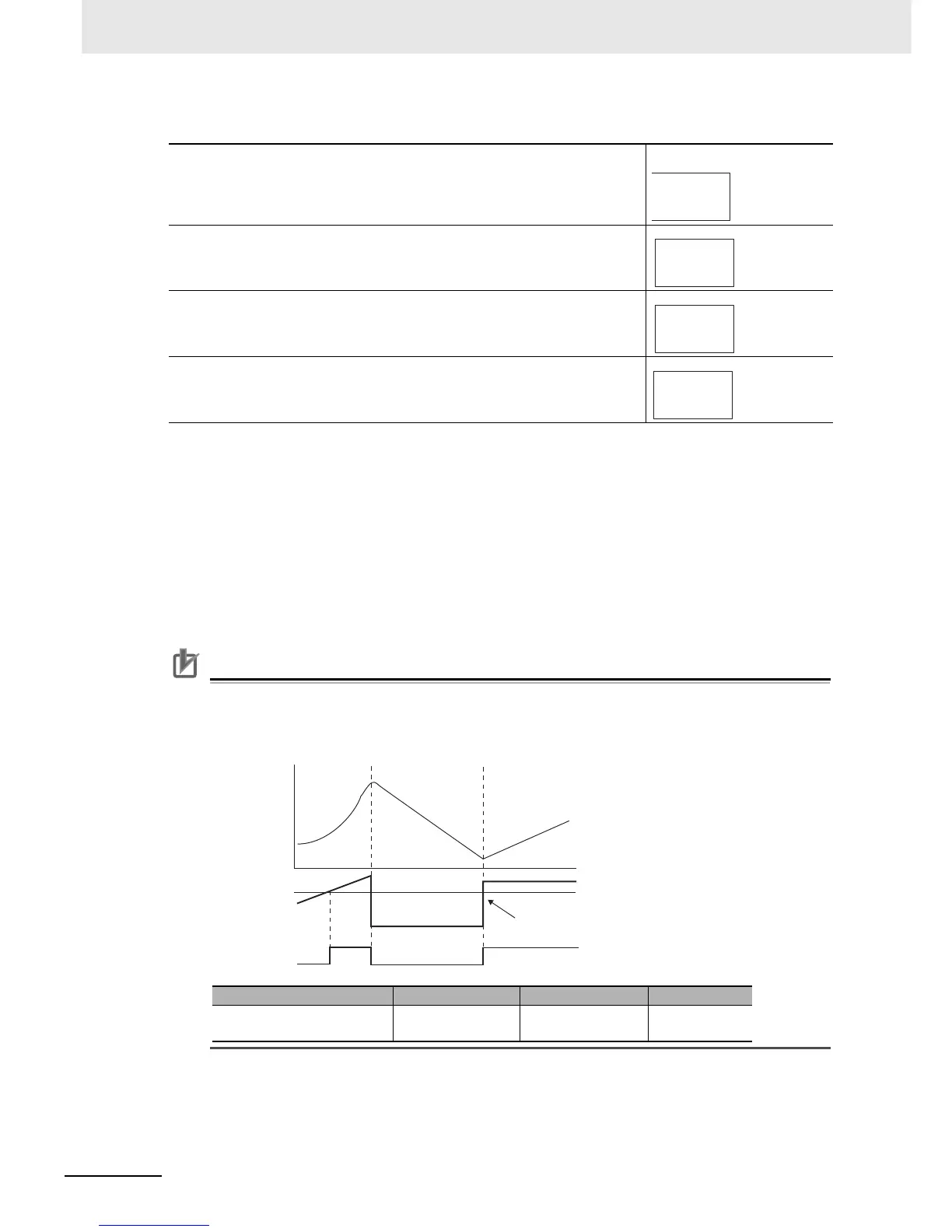
z PV Change Rate Alarm
The change width can be found for PV input values in any set period. Differences with previous
values in each set period are calculated, and an alarm is output if the result exceeds the alarm
value. The PV rate of change calculation period can be set in units of 50 ms.
If a positive value is set for the alarm value, the PV will operate as a change rate alarm in the rising
direction. If a negative value is set, the PV will operate as a change rate alarm in the falling direction.
Precautions for Correct Use
If a shorter PV rate of change calculation period is set, outputs set for the PV change rate alarm
function may repeatedly turn ON and OFF for a short period of time. It is therefore recommended
that the PV change rate alarm be used with the alarm latch turned ON.
• Setting the Alarm Value
1
Press the O Key for less than 1 second in the Operation
Level.
The display will change to the Program Setting Level.
Program Setting Level
2
Press the U or D Key to set 1.
3
Press M Key several times to select the Alarm Value 1 param-
eter.
4
Use the U Key to set the parameter to 10.
Parameter name Setting range Unit Default
PV Rate of Change
Calculation Period
1 to 999 Sampling cycle 20 (1 s)
0
d.prg
Display Program
Selection
1
d.prg
0
al-1
Alarm Value 1
10
al-1
0
OFF
PV
OFF
ON ON
Alarm value
Time
PV change width for PV rate
of change calculation period
Alarm function

 Loading...


