A - 17
A Appendices
E5@C-T Digital Temperature Controllers User’s Manual (H185)
A-5 Troubleshooting
A
A-3-2 E58-CIFQ2-E Conversion Cable
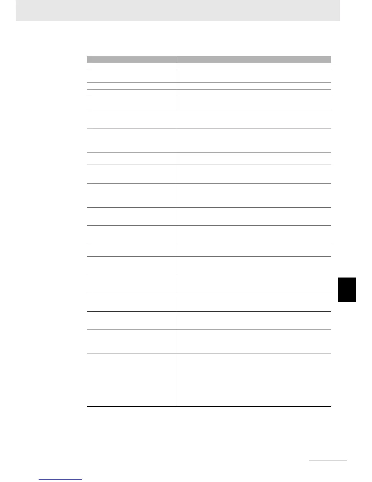
Symptom: Cannot Communicate or a Communications Error Occurs
* Also refer to the E5
@
C-T Digital Temperature Controllers Communications Manual (Cat. No. H186) for
details on errors.
Meaning Countermeasures
The communications wiring is not correct. Correct the wiring.
The communications line has become
disconnected.
Connect the communications line securely and tighten the screws.
The communications cable is broken. Replace the cable.
The communications cable is too long. The total cable length for RS-485 is 500 m max.
The wrong communications cable has
been used.
Use a shielded, AWG24 to AWG18 (cross-sectional area of 0.205 to 0.823
mm
2
) twisted-pair cable for the communications cable.
More than the specified number of
communications devices are connected to
the same communications path.
When 1:N communications are used, a maximum of 32 nodes may be
connected, including the host node.
An end node has not been set at each end
of the communications line.
Set or connect terminating resistance at each end of the line. If the
E5@C-T is the end node, 120-Ω (1/2-W) terminating resistance is used.
Be sure that the combined resistance with the host device is 54 Ω
minimum.
The specified power supply voltage is not
being supplied to the Controller.
Supply the specified power supply voltage.
The specified power supply voltage is not
being supplied to an Interface Converter
(such as the K3SC).
Supply the specified power supply voltage.
The same baud rate and communications
method are not being used by all of the
Controllers, host devices, and other
devices on the same communications line.
Set the same values for the baud rate, protocol, data length, stop bits, and
parity on all nodes.
The unit number specified in the
command frame is different from the unit
number set by the Controller.
Use the same unit number.
The same unit number as the Controller is
being used for another node on the same
communications line.
Set each unit number for only one node.
There is a mistake in programming the
host device.
Use a line monitor to check the commands. Check operation using a
sample program.
The host device is detecting the absence
of a response as an error before it
receives the response from the Controller.
Shorten the send data wait time in the Controller or increase the response
wait time in the host device.
The host device is detecting the absence
of a response as an error after
broadcasting a command.
The Controller does not return responses for broadcast commands.
The host device sent another command
before receiving a response from the
Controller.
The response must always be read after sending a command (except for
broadcast commands).
The host device sent the next command
too soon after receiving a response from
the Controller.
After receiving a response, wait at least 2 ms before sending the next
command.
The communications line became
unstable when Controller power was
turned ON or interrupted, and the host
device read the unstable status as data.
Initialize the reception buffer in the host device before sending the first
command and after turning OFF the power to the Controller.
The communications data was corrupted
from noise from the environment.
Try using a slower baud rate.
Separate the communications cable from the source of noise.
Use a shielded, twisted-pair cable for the communications cable.
Use as short a communications cable as possible, and do not lay or loop
extra cable.
To prevent inductive noise, do not run the communications cable parallel to
a power line.
If noise countermeasures are difficult to implement, use an Optical
Interface.

 Loading...


