2 Preparations
2 - 12
E5@C-T Digital Temperature Controllers User’s Manual (H185)
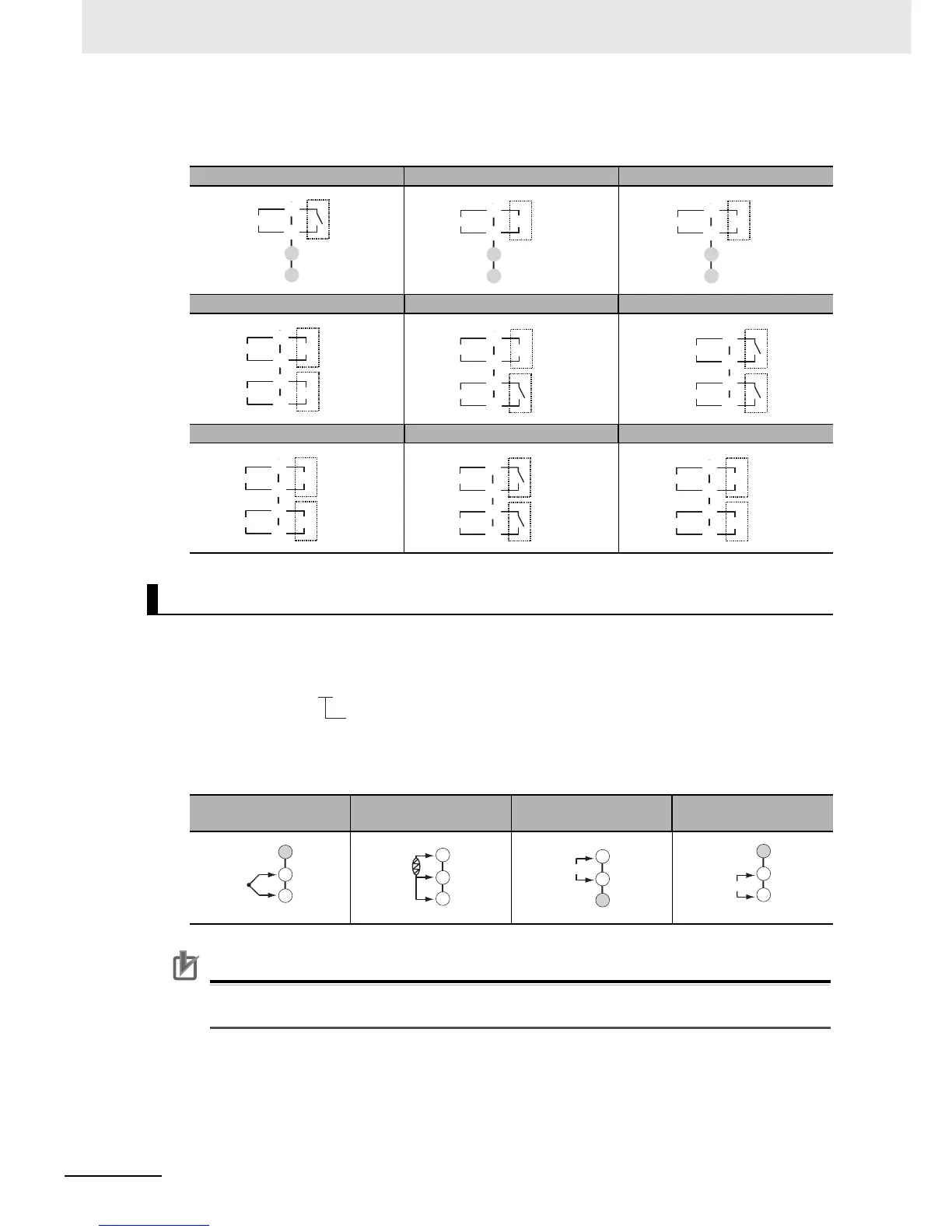
z Terminal Details
Do not connect anything to the terminals that are shaded gray.
z Model Numbers
All models have universal sensor inputs, so the code in the model number is always “M.”
z Terminal Details
Do not connect anything to the terminals that are shaded gray.
Precautions for Correct Use
When complying with EMC standards, the line connecting the sensor must be 30 m or less. If the
cable length exceeds 30 m, compliance with EMC standards will not be possible.
RX QX CX
QQ QR RR
CC PR CQ
Sensor Input
TC (thermocouple)
Pt (resistance
thermometer)
I (current) V (voltage)
C
E
D
F
Relay output
Control output 1
+
−
C
E
D
F
Voltage output
(for driving SSR)
Control output 1
+
C
E
D
F
Linear current
output
Control output 1
−
C
E
D
F
+
Voltage output
(for driving SSR)
Voltage output
(for driving SSR)
+
Control output 1
Control output 2
−
−
Relay output
C
E
D
F
+
Voltage output
(for driving SSR)
Control output 1
Control output 2
−
C
E
D
F
Relay output
Relay output
Control output 1
Control output 2
C
E
D
F
+
+
Control output 1
Control output 2
−
−
Linear current
output
Linear current
output
C
E
D
F
Relay output
Relay output
Open
Close
C
E
D
F
+
Voltage output
(for driving SSR)
+
Control output 1
Control output 2
−
−
Linear current
output
E5@C-T@@ @ @ @ M-@@@
Sensor input
−
+
22
23
24
A
B
B
22
23
24
+
−
mA
22
23
24
+
−
V
22
23
24

 Loading...


