18
Wiring Terminals Section 2-2
2-2-2 Precautions when Wiring
• Separate input leads and power lines in order to protect the E5AZ/E5EZ
and its lines from external noise.
• Use AWG24 (cross-sectional area: 0.205 mm
2
) to AWG14 (cross-sec-
tional area: 2.081 mm
2
) twisted-pair cable (stripping length: 5 to 6 mm).
• We recommend using solderless terminals when wiring the E5AZ/E5EZ.
• Tighten the terminal screws using a torque no greater than 0.74 to
0.90 N
⋅m.
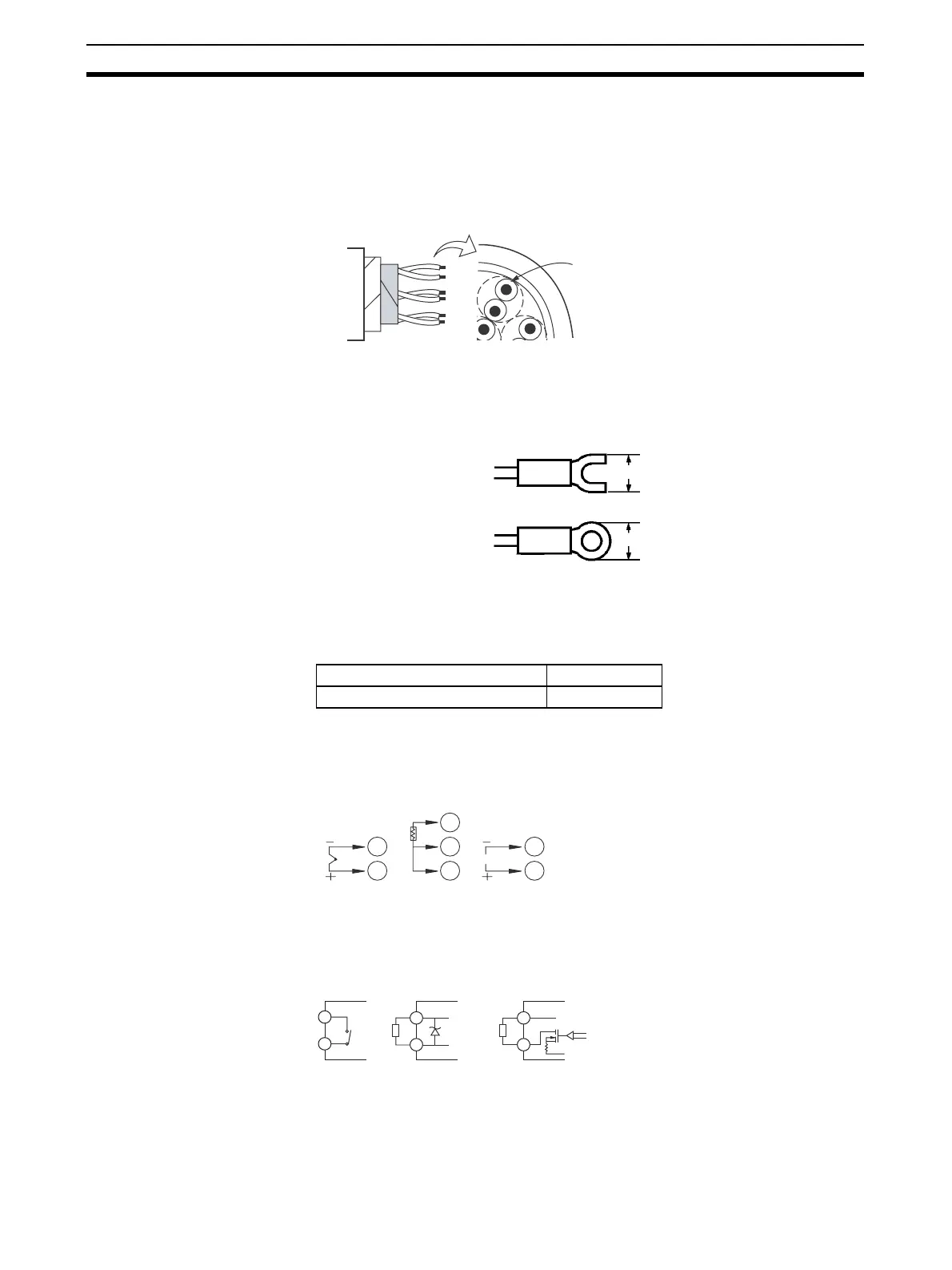
• Use the following type of solderless terminals for M3.5 screws.
2-2-3 Wiring
Power supply • Connect to terminals 1 and 2. The following table shows the specifica-
tions.
• Reinforced insulation is applied between the input power supply and the
I/O sections.
Input • Connect to terminals 9 to 11 as follows according to the input type.
Control output 1 • Terminals 7 and 8 are for control output. The following diagrams show the
available outputs and their internal equalizing circuits.
Cross-sectional area of conductor
AWG24: 0.205 mm
2
AWG14: 2.081 mm
2
7.2 mm max.
7.2 mm max.
Input power supply E5AZ/E5EZ
100 to 240 VAC, 50/60 Hz 10 VA
11
10
11
10
V
11
10
B
B’
9
A
Thermocouple Platinum
resistance
thermometer
Analog
input
7
8
7
8
L
+V
+
−
+
−
GND
7
8
L
+V
GND
Relay Volta
e Current

 Loading...