EasyManua.ls Logo

Omron E5AZ User Manual

Omron E5AZ
162 pages
To Next Page IconTo Next Page
To Previous Page IconTo Previous Page
Page #74 background imageLoading...
Page #74 background image
55
Shifting Input Values Section 4-1
2. Using equations (1) and (2) calculate the upper- and lower-limit tempera-
ture input shift values from the readout and temperature to be shifted that
you obtained in step 1.
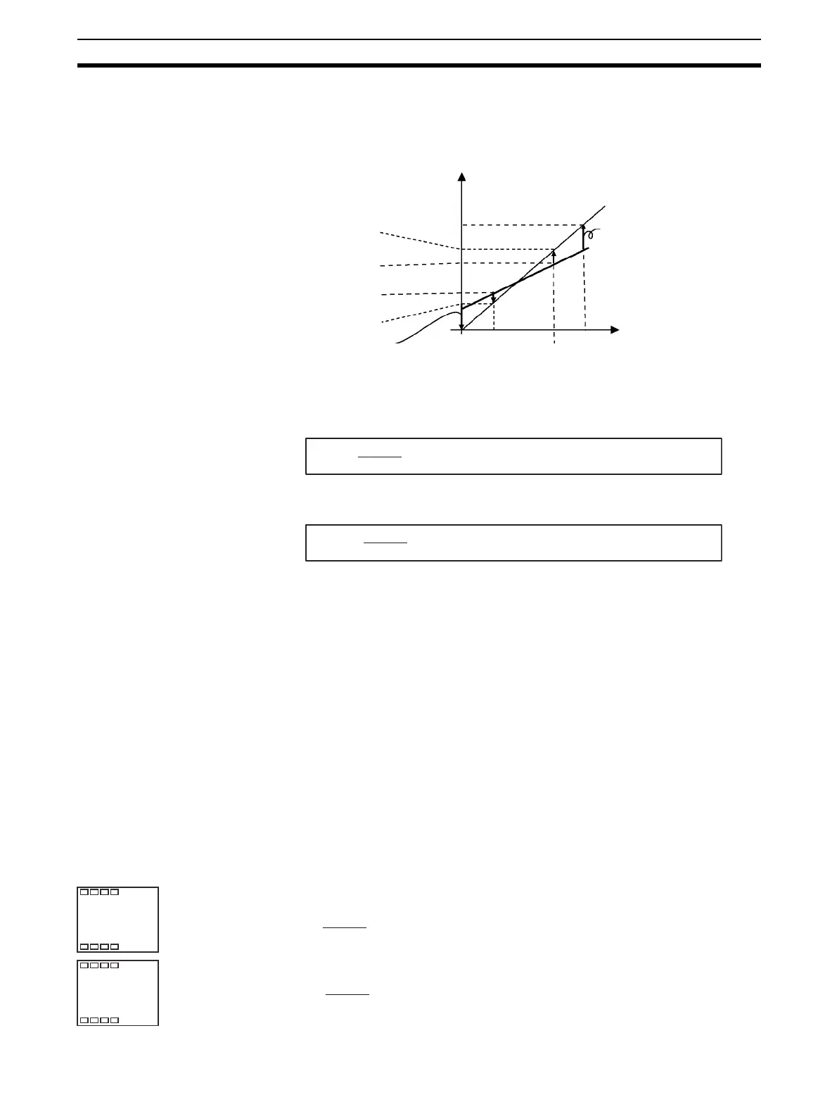
Figure 3 shows the effect of shift by two-point temperature input shift.
Use the following equation to calculate the lower-limit temperature input
shift value.
Use the following equation to calculate the upper-limit temperature input
shift value.
3. After you have set the calculated values to “insl and “insh”, check con-
troller readout (A) and control target temperature (B).
4. Although the input shift was carried out at two points, close to room tem-
perature (ambient temperature), and near to the set point, select points
close to each end of the sensor range to improve accuracy across the full
range of the sensor measurement range.
Note Before selecting these values, check that they will not damage the
controller if applied.
4-1-5 Example of Two-point Temperature Input Shift
In this example, we use the ES1B K 0 to 260°C specification. In equations 1
and 2, the set temperature lower limit YL is 0
°C and the set temperature upper
limit YH is 260
°C. Check the temperature of the control target.
The temperature input offset values can be calculated as shown below when
the Controller readout Y1 is 40
°C for a room temperature X1 of 25°C and
when the Controller readout Y2 is 105
°C for a set point temperature X2 of
110
°C.
Lower-limit temperature input shift value
Upper-limit temperature input shift value
Figure 3 Two-point Temperature Input Shift
Controller readout (A)
Set temperature
upper limit YH
(e.g. 260°C)
Temperature readout
after input shift X2 (e.g. 110°C)
Temperature readout
before input shift Y2 (e.g. 105°C)
Temperature readout
before input shift Y1 (e.g. 40°C)
Temperature readout
after input shift X1 (e.g. 25°C)
Lower-limit temperature
input shift value
X1 room temperature
(e.g. 25°C)
Set temperature
lower limit YL (e.g. 0°C)
Near X2 set point (e.g. 110°C)
Temperature readout of
control target (B)
Before shift
Upper-limit temperature
input shift value
After shift
0
insl
= × {(X2 Y2) (X1 Y1)} + (X1 Y1)...equation 1
YL Y1
Y2 Y1
insh
= × {(X2 Y2) (X1 Y1)} + (X1 Y1)...equation 2
YH Y1
Y2 Y1
Lower-limit
temperature
input shift value
Adjustment level
Upper-limit
temperature
input shift value
in5l
-27
C
in5h
53
C
insl
= × {(110 105) (25 40)} + (25 40) = 27.3 (°C)
0 40
105 40
insh
= × {(110 105) (25 40)} + (25 40) = 52.7 (°C)
260 40
105 40

Table of Contents

Question and Answer IconNeed help?

Do you have a question about the Omron E5AZ and is the answer not in the manual?

Omron E5AZ Specifications

General IconGeneral
BrandOmron
ModelE5AZ
CategoryTemperature Controller
LanguageEnglish

Summary

Preface and Document Overview

Visual Aids in Manual Navigation

Explains the use of headings in the left column for locating information.

Safety Precautions and Warnings

Definition of Precautionary Information

Explains the notation used for safety precautions and the meaning of CAUTION.

General CAUTION Warnings

Warns about output relay life, fire/electric shock risks, and handling precautions.

Operational and Electrical Safety Precautions

Warns about loose screws, unexpected operation, controller malfunction, and correct thermometer/input type.

Precautions for Safe Use

Environmental Usage Restrictions

Lists environments where the product should not be used, such as high humidity or direct sunlight.

Wiring Terminal Specifications

Specifies the type and size of crimped terminals required for wiring connections.

Power Supply and Handling Safety

Instructs to turn off power before handling and use proper power supply stabilization.

EEPROM Usage Considerations

Advises using RAM Mode for frequent data overwrites due to EEPROM's limited write life.

SECTION 1 Introduction to E5AZ/E5EZ Controllers

Names of Parts and Indicators

Identifies front panel components, displays, indicators, and keys of the E5AZ/E5EZ.

I/O Configuration and Main Functions

Details the controller's I/O configuration, inputs, outputs, and core functionalities.

Setting Level Configuration and Key Operations

Explains parameter levels and navigation using front panel keys.

Communications Functionality Overview

Describes the controller's communication capabilities for host computer interaction.

SECTION 2 Preparations for Operation

Installation Guidelines and Dimensions

Provides installation details, including dimensions and panel cutout specifications.

Option Unit Setup and Mounting

Explains the process of installing optional units like alarm and communication modules.

Wiring Terminals and Precautions

Details terminal arrangements and critical wiring precautions for safe and reliable connections.

Requests at Installation

To Ensure Prolonged Use

Provides guidelines on operating environment and temperature to ensure the product's prolonged use.

To Reduce the Influence of Noise

Offers methods to reduce induction noise by separating wires and using filters.

To Ensure High-precision Measurement

Details how to ensure high-precision measurements by using correct lead wires and proper installation.

SECTION 3 Basic Operation and Configuration

Initial Setting Examples and Procedures

Provides typical examples demonstrating initial setup procedures for controller parameters.

Setting Input Type and Temperature Unit

Guides on configuring the sensor input type and selecting the temperature unit (°C/°F).

Control Method Selection: PID vs. ON/OFF

Explains how to choose between 2-PID and ON/OFF control modes.

PID Constant Tuning: AT, ST, and Manual

Details methods for determining PID constants using auto-tuning, self-tuning, or manual setup.

Alarm Outputs Configuration

Covers setting alarm types, values, and delays for effective monitoring and alerts.

Using Heater Burnout Alarm (HBA)

Explains the setup and operation of the Heater Burnout Alarm (HBA) function.

SECTION 4 Applications Operations

Input Value Shifting Methods

Explains one-point and two-point methods for shifting input values to correct sensor readings.

Scaling Analog Inputs and Heating/Cooling Control

Guides on scaling analog inputs and executing heating/cooling control modes.

Event Inputs and Multi-SP Functionality

Details using event inputs for functions like multi-SP set point switching.

Setting SP Limits and SP Ramp Function

Covers setting SP upper/lower limits and using the SP ramp for controlled set point changes.

Advanced Function and Key Protect Level Access

Explains how to access advanced functions and use key protect levels for security.

SECTION 5 Parameters Reference

Parameter Levels: Protect, Operation, Adjustment

Describes the Protect, Operation, and Adjustment levels for parameter management.

Initial Setting and Communications Levels

Details the Initial Setting and Communications levels for basic configuration and interface settings.

Advanced Function Setting Level Parameters

Covers parameters for advanced functions like multi-SP, ramp, alarms, and I/O assignments.

Appendix: Supplementary Information

Controller Specifications and Characteristics

Lists detailed specifications, ratings, and characteristics of the E5AZ/E5EZ controllers.

Troubleshooting: Error Displays and Meanings

Explains common error displays, their meanings, and troubleshooting steps.

Parameter Operation List

Provides a comprehensive list of parameters for various levels with their settings and defaults.

Related product manuals