6.2 Preparing for Communications
E5CK
6–3
6.2 Preparing for Communications
For details on wiring when the communications function is used, see
Chapter 2 Preparations.
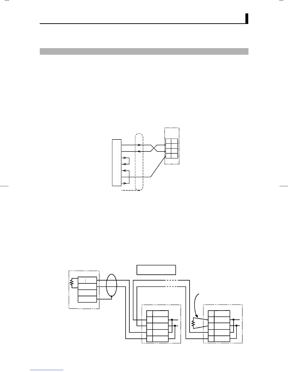
JCable connections
Ă• Only one controller can be connected to the host computer.
(1:1 connection)
Ă• The cable length should not exceed 15 meters.
Ă• Use shielded twistedĆpair cables (AWG28 or more) for the cables.
RS-232C
No.
13
SD
RD14
1SG
E5CK-T
IBM-PC/XT
DE-25
Female
DTE
(SD) TXD
(RD) RXD
(RS) RTS
(CS) CTS
(SG) COMMON
(ER) DTR
(DR) DSR
2
3
4
5
20
6
7
FG 1
25 pins
Ă• 1:1 or 1:N connections are allowed. In a 1:N connection, up to 32 controlĆ
lers including the host computer can be connected.
Ă• The total cable length should not exceed 500 meters.
Ă• Use shielded twistedĆpair cables (AWG28 or more) for the cables.
Ă• Attach terminators to the controllers at both ends of the series of conĆ
trollers connected in an open configuration. For example, in the followĆ
ing configuration, connect the terminator to unit No.30, and do not conĆ
nect terminators to unit Nos.0 to 29.
Ă• Use terminators having a resistance of 120 Ω (1/2 W). The total resisĆ
tance of both ends should be at least 54 Ω.
-
+
FG
RS-485
No.
32
31
RS-485
No.
32 A
B
31
Host computer
RS-485
Shielded cable
E5CK-T (No.0) E5CK-T (No.30)
Terminator
(120Ω 1/2W)
A
B
A < B : “1” Mark
A > B : “0” Space
19
20
A
B
19 A
B
20
F RS-232C
F RS-485

 Loading...


