CHAPTER 2 PREPARATIONS
E5CK
2–6
2.3 Wiring Terminals
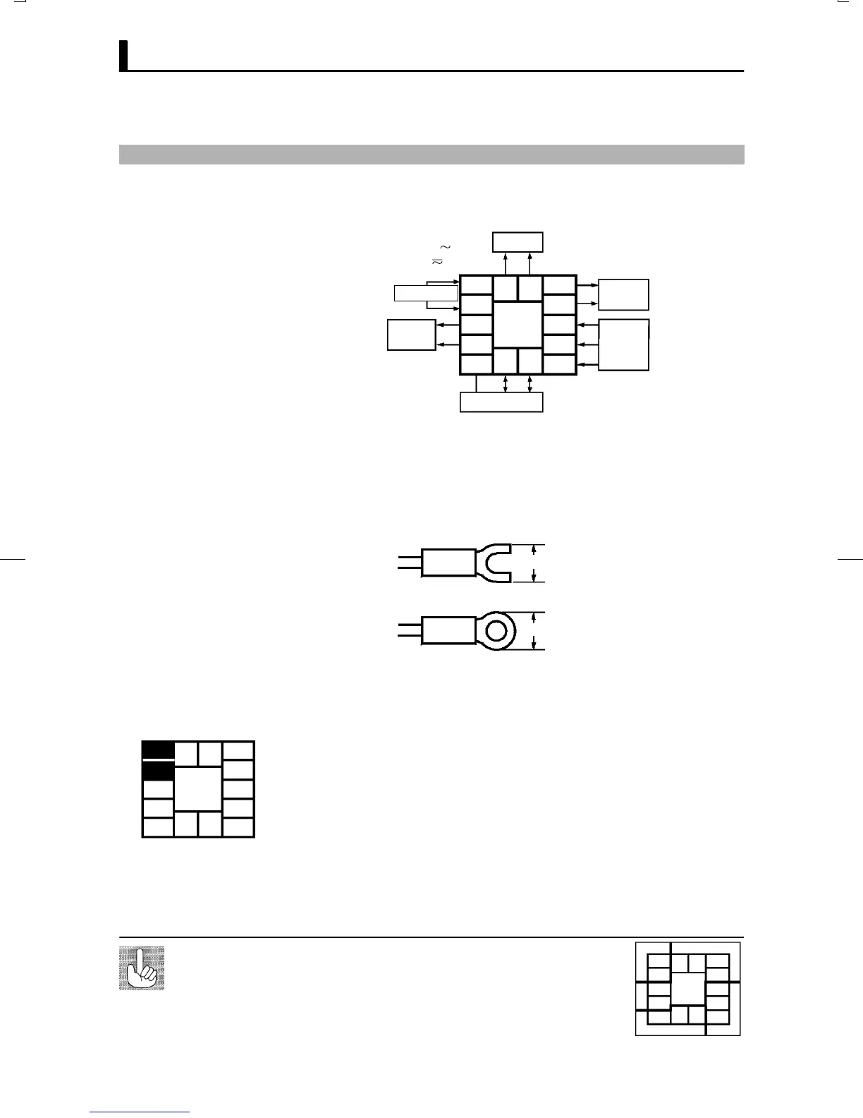
JTerminal arrangement
5
4
3
2
1
10
9
8
7
6
13 14
11 12
OUT1
OUT2
SUB1
OPTION
IN
AC100-240V
(AC/DC24V )
SOURCE
Ă• Separate input leads and power lines in order to protect the controller
and its lines from external noise.
Ă• We recommend using solderless terminals when wiring the controller.
Ă• Tighten the terminal screws using a torque no greater than 0.78 Nm
(8kgfcm).
Ă• Use the following type of solderless terminals for M3.5 screws.
7.2mm max.
7.2mm max.
In the following wiring diagrams, the left side of the terminal Nos. indiĆ
cates the inside of the controller.
Ă• Input power to terminals Nos. 4 and 5. Power specifications are as follows:
100 to 240 VAC, 50/60 Hz, 15 VA
or
24 VAC, 50/60 Hz, 6 VA
24 VDC, 3.5W
The E5CK has independent power supplies for each of the terĆ
minal blocks shown on the right. However, note that the
power supplies for blocks C (exclude relay output) and D are
shared for the following option unit.
Ă• Option unit : E53-CKB or E53-CKF
About the power
blocks
AC
5
4
3
2
1
10
9
8
7
6
C
DB
11 12
13 14
JPrecautions
when wiring
JWiring
F Power supply
5
4
3
2
1
10
9
8
7
6
13 14
11 12

 Loading...


