2.3 Wiring Terminals
E5CK
2–7
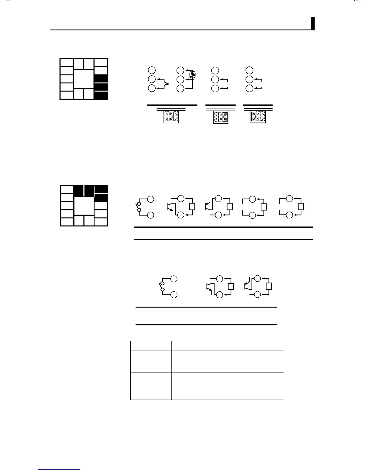
Ă• Connect the sensor input to terminal Nos. 6 to 8 as follows according to
the input type.
8
7
6
8
7
6
8
7
6
8
7
6
-
+
-
+
-
+
V
mA
TC ⋅ PT V I
Thermocouple Platinum resistance
thermometer
Voltage input Current input
Ă• Set the input type jumper inside the controller matched to the input
type. Set thermocouples and platinum resistance thermometer as temĆ
perature input to the shared jumper setting (TC/PT). For details on the
input type jumper, see page 2-2.
Ă• Terminal Nos. 11 and 12 are for control output 1 (OUT1). The following
diagrams show the available outputs and their internal equalizing circuits.
11
12
11
12
L
11
12
L
11
12
L
11
12
L
E53-R4R4 E53-Q4R4
E53-Q4Q4
E53-Q4HR4
E53-Q4HQ4H
E53-V44R4 E53-C4R4
E53-C4DR4
NPN PNP 0 to 10V 4 to 20mA
+v
+
-
+
-
+
-
+
-
GND
mA
Relay
V
GND
+v
Ă• Terminal Nos. 9 and 10 are for control output 2 (OUT2). The following
diagrams show the available outputs and their internal equalizing cirĆ
cuits.
10
9
10
9
L
10
9
L
+v
+
-
+
-
GND
E53-Q4Q4 E53-Q4HQ4H
NPN PNP
E53-R4R4 /E53-V44R4
E53-Q4R4 /E53-C4R4
E53-Q4HR4/E53-C4DR4
Relay
GND
+v
Ă• The following table shows the specifications for each output type.
Output Type
Specifications
Relay
Voltage (NPN)
Voltage (PNP)
250VAC, 3 A
12VDC, 20 mA (with short-circuit protection)
12VDC, 20 mA (with short-circuit protection)
0 to 10V
4 to 20mA
0 to 10VDC, Permissible load impedance:
1 kΩ min., Resolution: Approx. 2600
4 to 20 mA, Permissible load impedance:
500 Ω max., Resolution: Approx. 2600
F Input
5
4
3
2
1
10
9
8
7
6
13 14
11 12
F Control output
5
4
3
2
1
10
9
8
7
6
13 14
11 12

 Loading...


