CHAPTER 7 CALIBRATION
E5CK
7–2
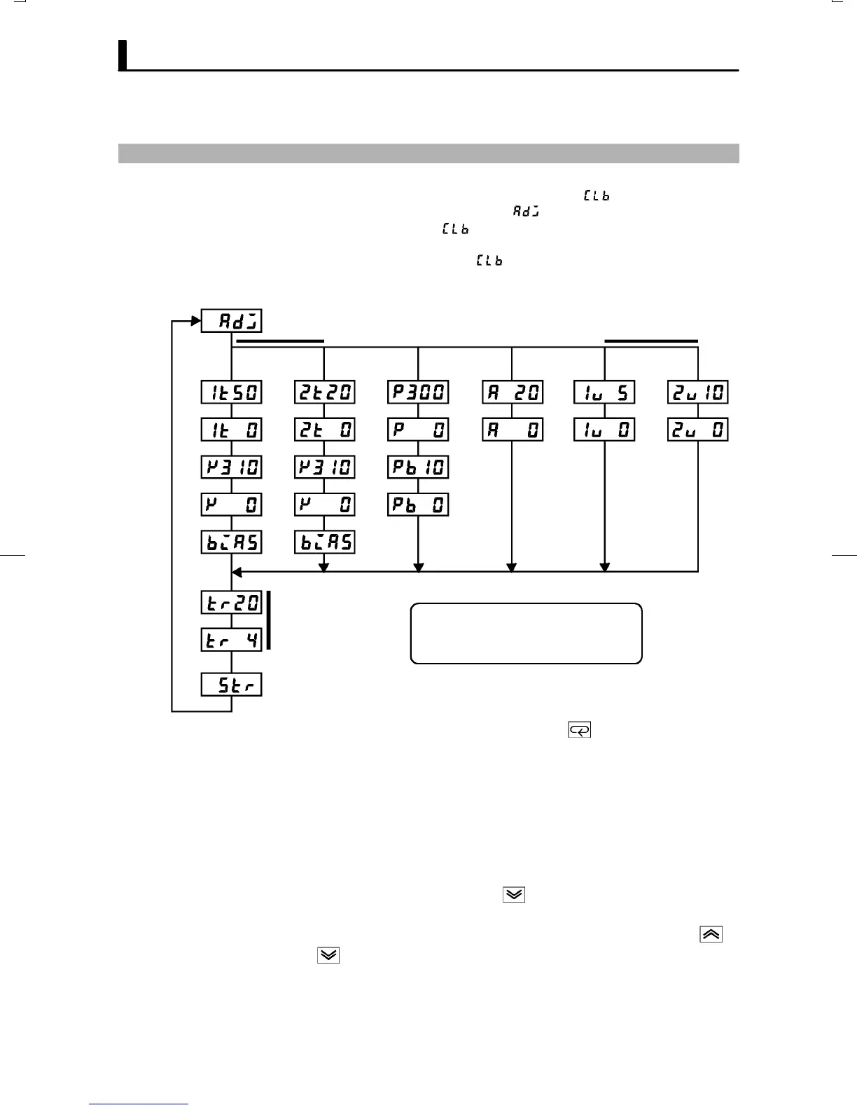
7.1 Parameter Structure
Ă• To calibrate the E5CKĆT controller, select [ĂĂ ] in the menu display
to select the calibration mode. [ĂĂ ] .is displayed.
Ă• However, note that [
] may not be displayed on the menu display
when, for example, the user is calibrating the E5CKĆT controller for the
first time. If this happens, [ ] is displayed by changing the security"
parameter (protect mode) to 0".
Ă• The parameters in the calibration mode are structure as follows:
0 to 10V0 to 5V 1 to 5V
Thermocouple
Thermocouple 1
Transfer output
Data storage
Platinum resistance
thermometer
Voltage inputCurrent input
Thermocouple 2
Thermocouple 1 : K1/J1/L1/E/N/W/PLII
Thermocouple 2 : K2/J2/L2/R/S/B/T/U
Platinum resistance
thermocouple
:JPt100/Pt100
Only when the
transfer output
function is sup-
ported
Ă• To select the desired parameter, press the key. Parameters are disĆ
played in the following order:
Calibration of inputs → Calibration of transfer output →
Storage of calibration data
If the E5CKĆT controller does not support the transfer output function,
calibration of transfer output is automatically deleted from the calibraĆ
tion procedure as follows:
Calibration of inputs → Storage of calibration data
Ă• Only inputs that have been set in the input type" parameter (setup
mode) can be calibrated. To temporarily store data for each of the calĆ
ibration parameters, press the
key for 1 second.
Ă• Transfer output can be calibrated only when the Communications unit
(E53ĆCKF) is set in the controller. To adjust data items, press the
or
keys.
Ă• The data store menu is displayed only when all calibration items have
temporarily been stored.
Ă• After calibrating input, you must always check indication accuracy. For
details, see page 7Ć12.

 Loading...


