EasyManua.ls Logo

Omron E5CK User Manual

Omron E5CK
186 pages
To Next Page IconTo Next Page
To Previous Page IconTo Previous Page
Page #66 background imageLoading...
Page #66 background image
CHAPTER 4 APPLIED OPERATION
E5CK
4–10
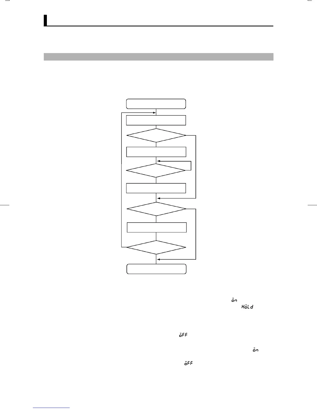
4.4 Program Operation
Ă Steps in currently executing programs can be forcibly stopped (Hold)
and advanced (Advance).
Ă Hold and Advance operation is according to the following procedure:
Run in level 0 mode
Check step No.
Hold?
Hold = ON
Continue
End of hold?
End
Hold = OFF
Advance
Advance = ON
Continue
End of advance
End
End: To program operation
Y
Y
N
N
Ă Execute hold/advance operation while making sure the step No. in the
step No. monitor" parameter (level 0 mode).
Ă When the hold" parameter (level 0 mode) is set to  : ON", step time
counting is paused (held), and the HOLD" LED lights. [
] and the
SP appear alternately on the No.2 display when in the PV/Present SP"
parameter.
Ă Hold is canceled time counting is restarted by one of the following condiĆ
tions: hold" parameter =  : OFF", Run, Reset, End operation usĆ
ing advance instruction
Ă Each time that advance" parameter (level 0 mode) is set to  : ON",
the program advances one step. With each step advance, the Advance"
parameter setting returns to  : OFF".
Ă If the advance function is executed with the program in a hold state, the
hold state is continued in the next step.
JHold/advance

Table of Contents

Other manuals for Omron E5CK

Question and Answer IconNeed help?

Do you have a question about the Omron E5CK and is the answer not in the manual?

Omron E5CK Specifications

General IconGeneral
Ambient Operating Temperature-10 to 55°C
Protection RatingIP20
Control TypePID
Input TypeThermocouple, RTD
Output TypeRelay, Voltage, Current
Power Supply Voltage100 to 240 VAC
Mounting TypePanel
Display TypeDigital
Control OutputRelay, Voltage, Current
Alarm OutputRelay
Dimensions48 x 48 x 78 mm
Ambient Operating Humidity25% to 85% RH

Summary

Preface

Precautions in Using the Product

Essential safety precautions and guidelines for using the E5CK-T controller to prevent hazards.

PRECAUTIONS ON SAFETY

Marks For Ensuring Safe Use and Their Meanings

Details the meaning of safety marks like WARNING to ensure safe handling and prevent injury.

CHAPTER 1 INTRODUCTION

1.1 Names of Parts

Identifies and describes the main parts and front panel components of the E5CK-T controller.

1.2 Input and Output

Details the types of inputs supported and the various control and auxiliary outputs available.

CHAPTER 2 PREPARATIONS

2.1 Setup

Guides on drawing out the internal mechanism and setting the input type jumper.

2.3 Wiring Terminals

Details the terminal arrangement, precautions, and wiring diagrams for power supply and inputs/outputs.

CHAPTER 3 BASIC OPERATION

3.8 Adjusting Control Operation

Covers changing programs, set points, time values, manual operation, and auto-tuning.

CHAPTER 4 APPLIED OPERATION

CHAPTER 5 PARAMETERS

CHAPTER 6 USING THE COMMUNICATIONS FUNCTION

CHAPTER 7 CALIBRATION

7.2 Calibrating Thermocouples

Provides step-by-step instructions for calibrating thermocouple inputs.

7.4 Calibrating Current Input

Details the procedure for calibrating current input signals.

CHAPTER 8 TROUBLESHOOTING

8.1 Initial Checks

Lists initial checks for power supply, input jumper, and wiring when troubleshooting.

8.2 How to Use the Error Display

Explains how to interpret error codes displayed on the controller and their remedies.

Related product manuals