EasyManua.ls Logo

Omron E5CK User Manual

Omron E5CK
186 pages
To Next Page IconTo Next Page
To Previous Page IconTo Previous Page
Page #131 background imageLoading...
Page #131 background image
6.3 Command Structure
E5CK
6–5
6.3 Command Structure
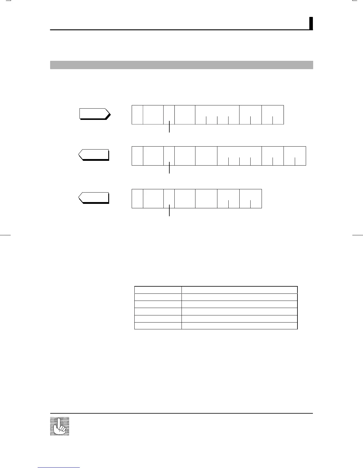
Command structure is as follows. Each command is paired with a reĆ
sponse.
Unit
No.
Command
code
Data
FCS
CR
Command type
@
*
2B 1B 2B 4B 2B 2B
Command
Unit
No.
Command
code
Data
FCS
Command type
CR
End
code
@
*
2B 1B 2B 4B 2B 2B2B
Response
End code = 00
Unit
No.
Command
code
FCS
Command type
CR
End
code
@
*
2B 1B 2B 2B 2B2B
End code = 00
Response
Ă @"
The start character. This character must be inserted before the leading
byte.
Ă Unit No.
Specifies the unit No." of the E5CKĆT. If there are two or more transĆ
mission destinations, specify the desired destination using unit No."
Ă Command type
Code Command type
1 Parameter read
2 Parameter write
3 Special command
4 Program parameter read
5 Program parameter write
Ă Command code
Specifies the command for each command type. With parameter read/
write commands and program parameter read/write commands, this beĆ
comes the parameter No.
Ă Data
Specifies the set value or setting content. With the parameter read and
program parameter read commands, set dummy data 0000". In the reĆ
sponse, this is inserted only when the end code is 00".
Currently, if a command is used for invalid parameters (parameters that do not satisĆ
fy the conditions of use in Chapter 5), the undefined" error (end code: IC) response
is returned.
About invalid
parameters

Table of Contents

Other manuals for Omron E5CK

Question and Answer IconNeed help?

Do you have a question about the Omron E5CK and is the answer not in the manual?

Omron E5CK Specifications

General IconGeneral
Ambient Operating Temperature-10 to 55°C
Protection RatingIP20
Control TypePID
Input TypeThermocouple, RTD
Output TypeRelay, Voltage, Current
Power Supply Voltage100 to 240 VAC
Mounting TypePanel
Display TypeDigital
Control OutputRelay, Voltage, Current
Alarm OutputRelay
Dimensions48 x 48 x 78 mm
Ambient Operating Humidity25% to 85% RH

Summary

Preface

Precautions in Using the Product

Essential safety precautions and guidelines for using the E5CK-T controller to prevent hazards.

PRECAUTIONS ON SAFETY

Marks For Ensuring Safe Use and Their Meanings

Details the meaning of safety marks like WARNING to ensure safe handling and prevent injury.

CHAPTER 1 INTRODUCTION

1.1 Names of Parts

Identifies and describes the main parts and front panel components of the E5CK-T controller.

1.2 Input and Output

Details the types of inputs supported and the various control and auxiliary outputs available.

CHAPTER 2 PREPARATIONS

2.1 Setup

Guides on drawing out the internal mechanism and setting the input type jumper.

2.3 Wiring Terminals

Details the terminal arrangement, precautions, and wiring diagrams for power supply and inputs/outputs.

CHAPTER 3 BASIC OPERATION

3.8 Adjusting Control Operation

Covers changing programs, set points, time values, manual operation, and auto-tuning.

CHAPTER 4 APPLIED OPERATION

CHAPTER 5 PARAMETERS

CHAPTER 6 USING THE COMMUNICATIONS FUNCTION

CHAPTER 7 CALIBRATION

7.2 Calibrating Thermocouples

Provides step-by-step instructions for calibrating thermocouple inputs.

7.4 Calibrating Current Input

Details the procedure for calibrating current input signals.

CHAPTER 8 TROUBLESHOOTING

8.1 Initial Checks

Lists initial checks for power supply, input jumper, and wiring when troubleshooting.

8.2 How to Use the Error Display

Explains how to interpret error codes displayed on the controller and their remedies.

Related product manuals