2.1 Setup
E5CK
2–3
JSetting up the output unit
The following table shows the output units that can be set in the E5CK
controller.
Model
Specifications
(control output 1/control output 2)
E53-R4R4
E53-Q4R4
E53-Q4HR4
E53-C4R4
E53-C4DR4
E53-V44R4
E53-Q4Q4
E53-Q4HQ4H
Relay/Relay
Voltage (NPN)/Relay
Voltage (PNP)/Relay
4 to 20 mA/Relay
0 to 20 mA/Relay
0 to 10 V/Relay
Voltage (NPN)/Voltage (NPN)
Voltage (PNP)/Voltage (PNP)
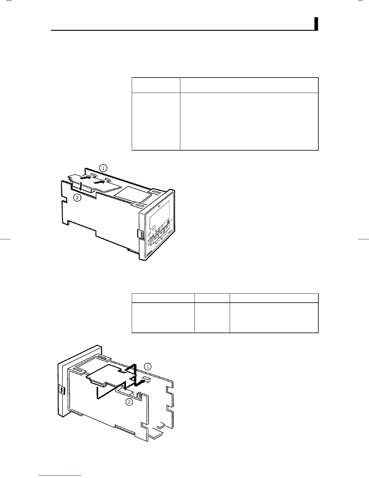
F Setup
(1) Two rectangular holes for slotting are proĆ
vided on the power board (on right side of
controller). Fit the two protrusions on the
output unit into these two holes.
(2) With the output unit fitted into the power
board, fit the output unit into the connector
on the control board (on left side of controlĆ
ler).
JSetting up the option unit
The following table shows the option units that can be connected to the
E5CK controller.
Unit Model Specifications
Communications unit
Communications unit
Input unit
Communications unit
E53-CK01
E53-CK03
E53-CKB
E53-CKF
Communications (RS-232C)
Communications (RS-485)
Event input: 1 input
Transfer output: 4 to 20 mA
F Setup
(1) Place the controller with its bottom facing
up, and fit the board horizontally into the
connector on the power board (on right side
of controller).
(2) With the power board connected, fit the
board vertically into the connector on the
control board (on left side of controller).
F Output unit list
F Option unit list

 Loading...


