3.1 Convention Used in this Chapter
E5CK
3–3
This description assumes that the controller is operated under the followĆ
ing conditions.
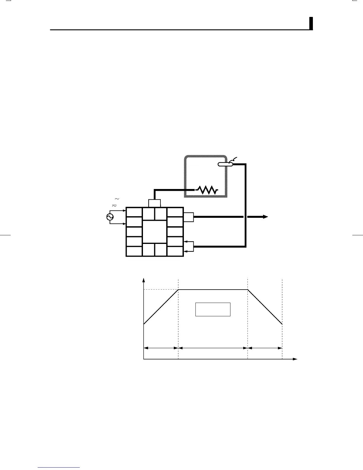
Ă• A K thermocouple is used as the input.
Ă• Control output (heat), alarm 1 and alarm 2 functions are assigned to
control output 1," control output 2" and auxiliary output 1, respecĆ
tively. Of these, only control output 1 and auxiliary output 1 are used.
Ă• The relay output unit is mounted at control output 1.
Ă• The upperĆlimit alarm is set as alarm 2. The alarm is output when the
temperature exceeds 10C with respect to the PV.
Ă• The program is made up of one pattern comprising four steps.
Ă• The following figures show terminal wiring and the program used in the
setting examples.
5
4
3
2
1
10
9
8
7
6
13 14
11 12
OUT1
OUT2
Humidifier
Control target
Temperature sensor
K thermocouple
Alarm 1
(deviation upper-and
lower-limit)
E5CK–T
AC100-240V
(AC/DC24V )
Step 1 Step 2 Step 3
Pattern 0
Time: hr, min
0.20 0.40 0.20
50
100
SP
F Setup examples

 Loading...


