2 - 71
2 Preparations
E5@C Digital Temperature Controllers User’s Manual (H174)
2-2 Using the Terminals
2
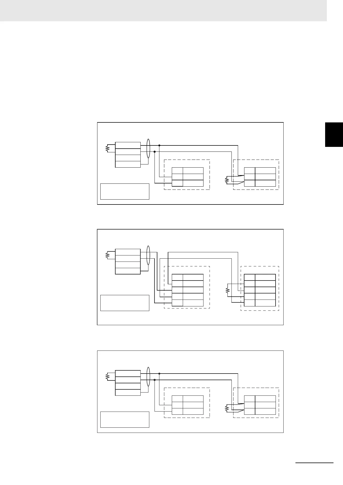
2-2-10 Wiring
Communications
RS-485
Models with an option number of 002 to 004, 008, 009, 012, 014, or 015 support RS-485 communications.
To use communications with the E5CC, E5AC, or E5EC, connect the communications cable to terminals 13
and 14, with the E5CC-B or E5EC-B, to terminals 17 or 18 and 19 or 20, with the E5DC, to terminals 3 and 4,
with the E5DC-B, to terminals 5 and 6, and with the E5GC, to terminals 7 and 8.
Communications Unit Connection Diagram
E5CC/E5EC/E5AC
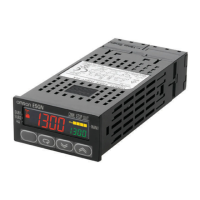
E5CC-B/EC-B
E5DC
No.
14
13
No.
14
13
RS-485
E5CC/E5EC/E5AC (No. 1)
RS-485
E5CC/E5EC/E5AC
(No. 31)
100 Ω
A (−)
B (+)
A (−)
B (+)
−
+
FG
RS-485
Host computer
Shield
Terminator (120 Ω, 1/2 W)
Abbreviation
Abbreviation
A < B: [1] Mark
A > B: [0] Space
Terminator (120 Ω, 1/2 W)
−
+
FG
No.
Abbreviation
20 A(
−
)
19 A(
−
)
18 B(+)
17 B(+)
No.
Abbreviation
20 A(
−
)
19 A(
−
)
18 B(+)
17 B(+)
RS-485
E5CC-B/E5EC-B (No. 1)
RS-485
E5CC-B/E5EC-B
(No. 31)
100 Ω
RS-485
host computer
Shield
Shield
A < B: [1] Mark
A > B: [0] Space
Terminator (120 Ω, 1/2 W)
−
+
FG
No.
Abbreviation
4 A(−)
3 B(+)
No.
Abbreviation
4 A(−)
3 B(+)
RS-485
E5DC (No. 1)
RS-485
E5DC (No. 31)
100 Ω
RS-485
host computer
Shield
A < B: "1" Mark
A > B: [0] Space