4 - 47
4 Basic Operation
E5@C Digital Temperature Controllers User’s Manual (H174)
4-12 Using Heater Burnout (HB) and Heater Short (HS) Alarms (Not
Supported for Position-proportional Models.)
4
4-12-5 Application Examples
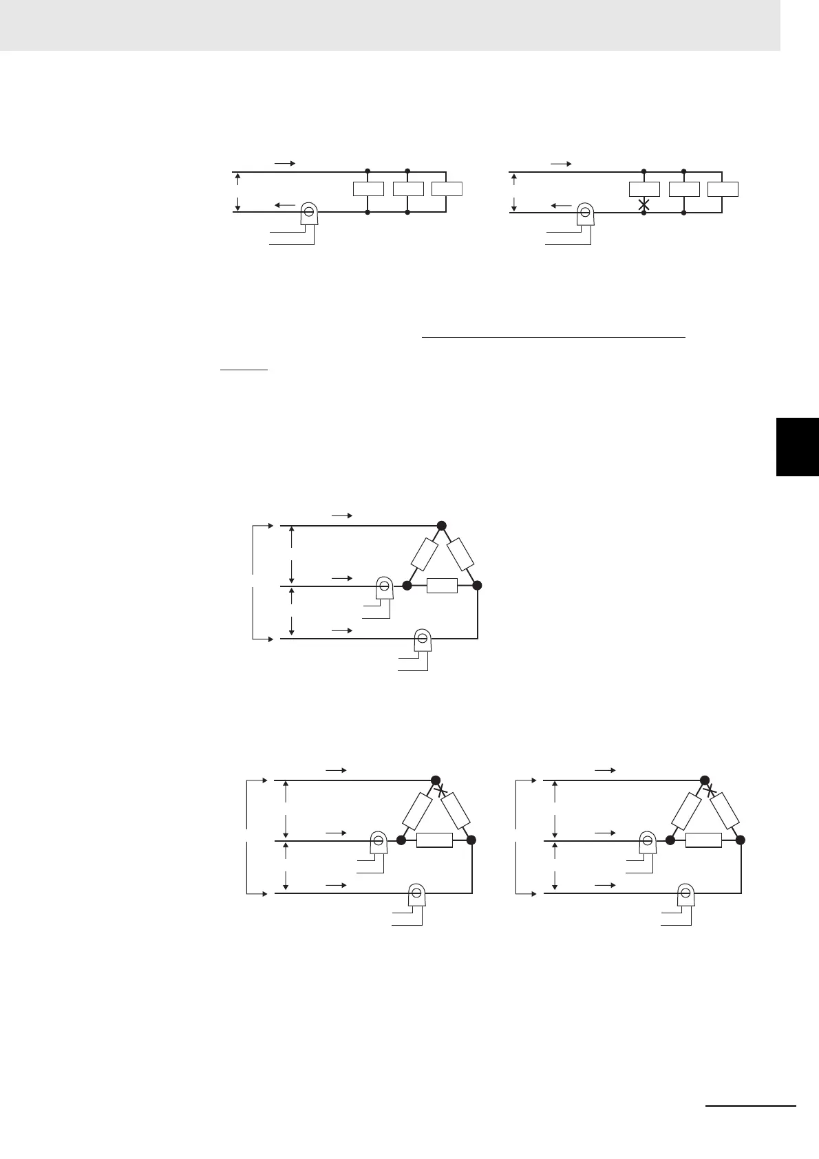
Example: Using Three 200-VAC, 1-kW Heaters
The heater power supply provides 15 A when the current is normal, and 10 A when there is
a burnout, so the heater burnout detection current is calculated as follows:
(2) Three-phase Heaters
(a) Delta Connecting Lines
Example: Using Three 200-VAC, 2-kW Heaters
The current when each phase is normal is 17.3 A (≈ √3 × 10 A).
The heater burnout current when there is a burnout at the load line is as follows:
(Heater burnout detection current) = (17.3 + 15) / 2
= 16.15 [A]
Normal Burnout
Normal
Normal Burnout
Current when there is a burnout =
10 A × √3 × (√3/2) = 15 A
Current when there is a burnout =
10 A × √3 × (1/√3) = 10 A
CT
15 A
15 A
Load
200 V
Load Load
Product
To CT input
CT
10 A
10 A
Load
200 V
Load Load
Product
To CT input
Burnout
Heater burnout detection current =
(Normal current) + (Heater burnout current)
2
=
15 + 10
2
= 12.5 [A]
CT
CT
Load
Load
Load
17.3 A
17.3 A
17.3 A
200 V
200 V
200 V
Product
To CT input
Product
To CT input
Burnou
Product
To CT input
Product
To CT input
CT
CT
Load
Load
Load
10 A
17.3 A
10 A
200 V
200 V
200 V
Burnout
Product
To CT input
Product
To CT input
CT
CT
Load
Load
Load
10 A
17.3 A
10 A
200 V
200 V
200 V

 Loading...