4 Basic Operation
4 - 48
E5@C Digital Temperature Controllers User’s Manual (H174)
The heater burnout current when there is a burnout at the load is as follows:
(Heater burnout detection current) = (17.3 + 10) / 2
= 13.65 [A]
To enable detection in either case, use 16.1 A as the heater burnout detection current.
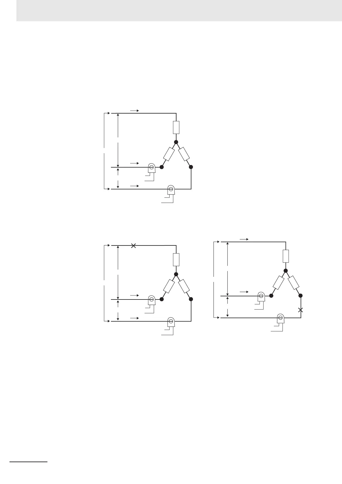
(b) Star Connecting Lines
Example: Using Three 200-VAC, 2-kW Heaters
The current when each phase is normal is 5.8 A (≈ 10 A × (1 /√3)).
The heater burnout detection current for this connecting line is 5.4 A (= (5.8 + 5) / 2).
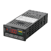
Normal
Normal Burnout
Current when there is a burnout =
10 A × (1/ √3) × (√3/2) = 5 A
Current when there is a burnout =
10 A × (1/ √3) × (√3/2) = 5 A
CT
CT
Load
Load
Load
5.8 A
5.8 A
5.8 A
200 V
200 V
200 V
Product
To CT input
Product
To CT input
Load (such as a heater)
CT
CT
Load
Load
Load
5 A
5 A
200 V
200 V
200 V
Burnout
Load (such as a heater)
Product
To CT input
Product
To CT input
CT
CT
Load
Load
Load
5 A
5 A
200 V
200 V
200 V
Load (such as a heater)
Product
To CT input
Product
To CT input
Burnout