A - 37
A Appendices
E5@C Digital Temperature Controllers User’s Manual (H174)
A-6 Parameter Operation Lists
A
A-6-6 Advanced Function Setting Level
*1 If the Manual MV Limit Enable parameter is set to ON, the setting range will be the MV lower limit to the
MV upper limit.
*2 The setting ranges are different for relay and voltage outputs (for driving SSR) and for linear current
outputs.
*3 This parameter can be set when the Program Pattern parameter is set to OFF, but the function will be
disabled.
*4 WR1 to WR8 are not displayed when the logic operation function is not used.
*5 With the E5CC-U, E5DC, E5DC-B or E5GC, if the control output is a linear current output, the control
output can be used as a simple transfer output. (The E5CC-U must be manufactured in May 2014 or later
(version 2.2 or higher) and the E5DC must be manufactured in July 2014 or later (version 2.2 or higher).)
*6 You can select seconds (S) only for the E5DC, E5DC-B and E5GC. (The E5DC must be manufactured in
July 2014 or later (version 2.2 or higher).)
*7 You can select the status display message (WR) only for the E5DC, E5DC-B and E5GC. (The E5DC
must be manufactured in July 2014 or later (version 2.2 or higher).)
*8 This parameter is not supported for E5CC, E5EC, and E5AC version 2.0 or lower.
*9 You can use this parameter only with the E5EC-PR@-8@@ or E5AC-PR@-8@@. (The Digital Controller
must be manufactured in August 2014 or later (version 2.2 or higher).)
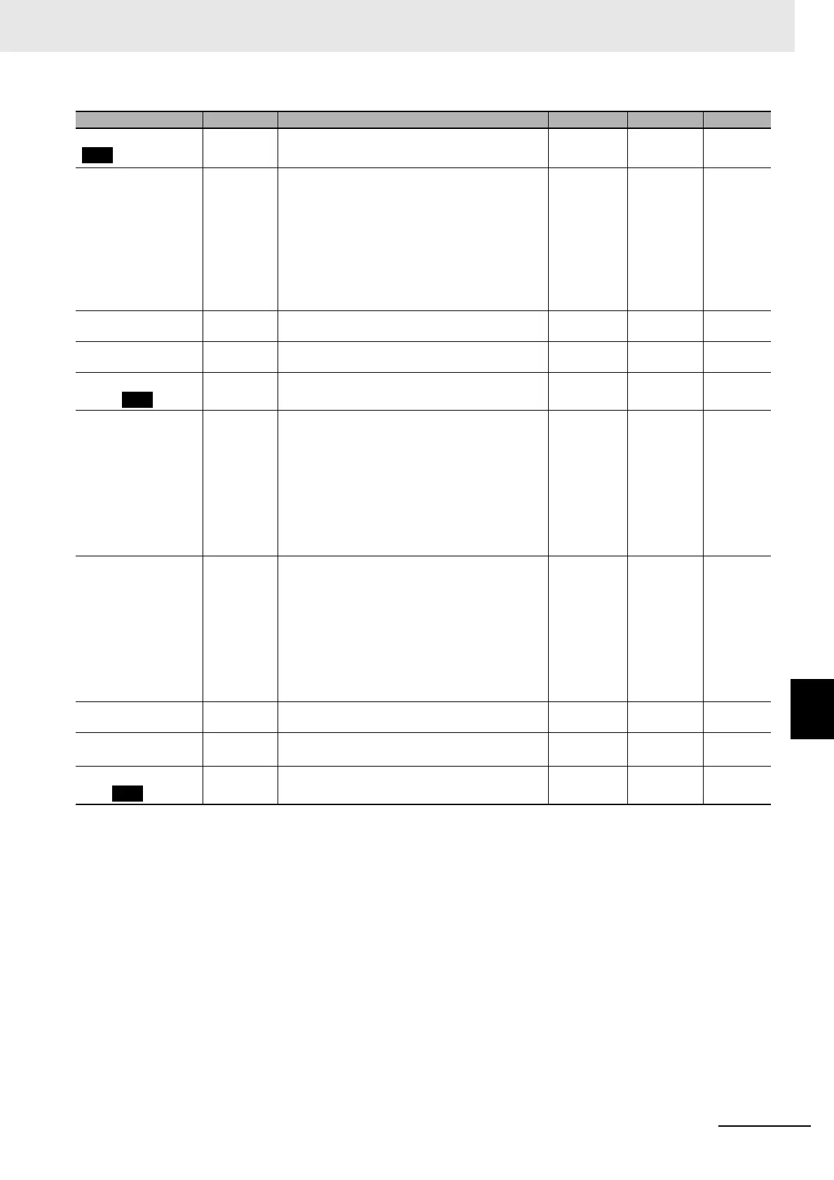
Monitor/Setting Item 5 pfd5 Same as Monitor/Setting Item 1. 0 None
PV/SP No. 1 Display
Selection
spd1 0: Nothing is displayed.
1: PV/SP/Nothing displayed
2: PV/Nothing displayed/Nothing displayed
3: SP/SP (character display)/Nothing displayed
4: PV/SP/MV (valve opening for
Position-proportional Models)
5: PV/SP/Multi-SP No.
6: PV/SP/Soak time remain
7: PV/SP/Internal SP (ramp SP)
8: PV/SP/Alarm value 1
4
*6
None
PV/SP No. 2 Display
Selection
spd2 Same as PV/SP No. 1 Display Selection. 0 None
MV Display Selection odsl O: MV (Heating)
C-O: MV (Cooling)
o, c-o
0 None
PV Decimal Point
Display
pvdp OFF, ON
off, on
ON None
PV Status Display
Function
pvst OFF: OFF
MANU: Manual
STOP: Stop
ALM1: Alarm 1
ALM2: Alarm 2
ALM3: Alarm 3
ALM4: Alarm 4
ALM: OR of alarms 1 to 4
HA: Heater alarm
WR: Status display message
*7
off
manu
stop
alm1
alm2
alm3
alm4
alm
ha
wr
OFF None
SV Status Display
Function
svst OFF: OFF
MANU: Manual
STOP: Stop
ALM1: Alarm 1
ALM2: Alarm 2
ALM3: Alarm 3
ALM4: Alarm 4
ALM: OR of alarms 1 to 4
HA: Heater alarm
WR: Status display message
*7
off
manu
stop
alm1
alm2
alm3
alm4
alm
ha
wr
OFF None
Display Refresh Period d.ref OFF, 0.25, 0.5, 1.0 off, 0.25,
0.5, 1.0
0.25 Second
LCT Cooling Output
Minimum ON Time
*8
lcmt 0.1 to 1.0 0.2 Second
Move to Calibration
Level
cmoV −1999 to 9999 0 None
Parameters Characters Setting (monitor) value Display Default Unit