2 - 21
2 Preparations
E5@C Digital Temperature Controllers User’s Manual (H174)
2-1 Installation
2
2-1-3 Mounting
E5GC
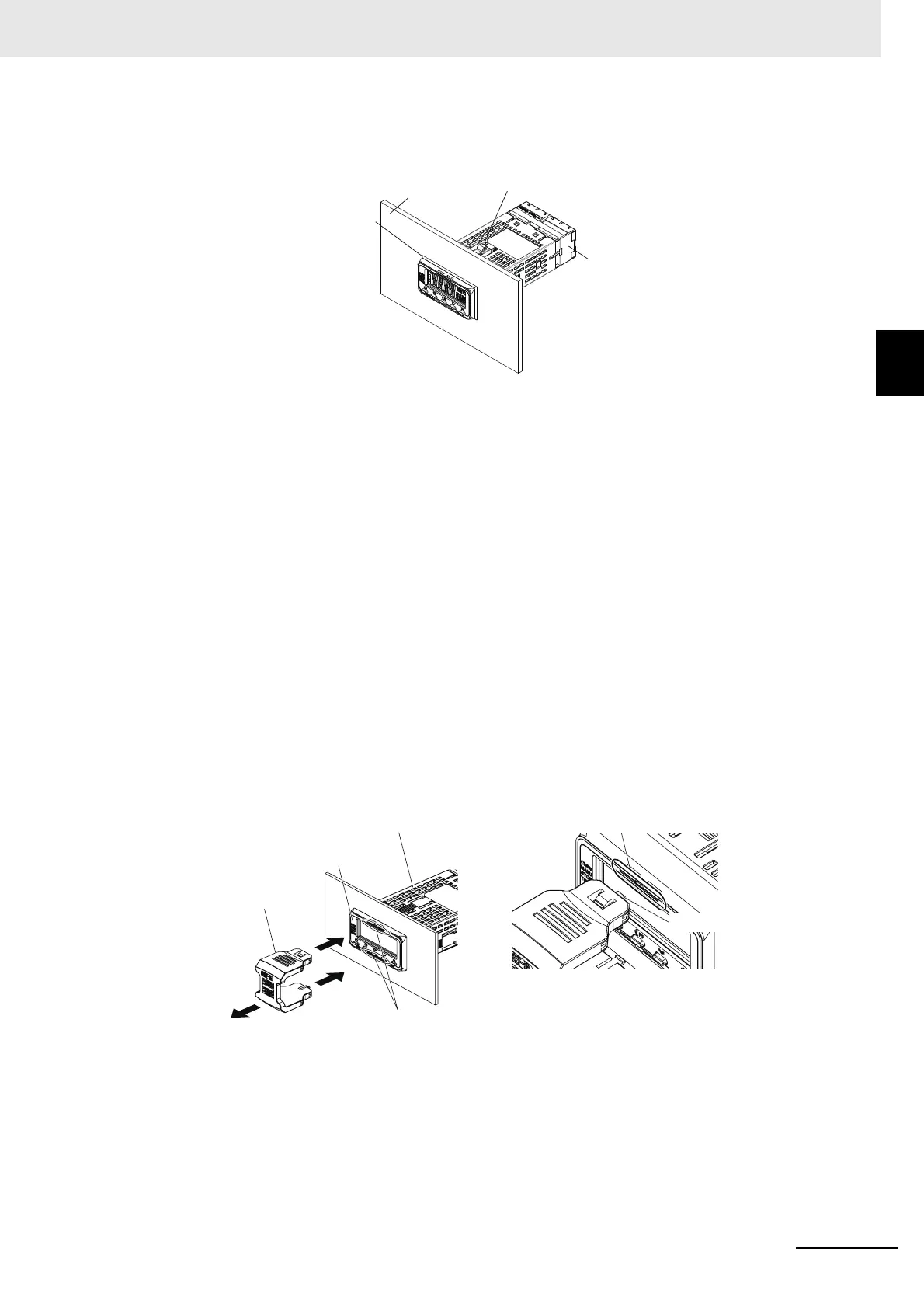
Mounting to the Panel
(1) When waterproofing is required, insert the Waterproof Packing on the backside of the front
panel. Digital Controllers cannot be waterproofed when they are mounted side by side.
(2) Insert the E5GC into the mounting hole in the panel.
(3) Use two Adapters, either on the top and bottom or on the right and left.
(4) Push the Adapter from the terminals up to the panel, and temporarily fasten the Digital
Controller.
(5) Tighten the two fastening screws on each Adapter. Alternately tighten the two screws little
by little to maintain a balance. Tighten the screws to a torque of 0.29 to 0.39 N·m.
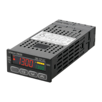
Drawing Out the Interior Body of the E5GC to Replace It
You can use the Y92F-55 Draw-out Jig to remove the interior body of the Digital Controller from the case to
perform maintenance without removing the terminal leads. This is possible for only the E5GC. Check the
specifications of the case and Digital Controller before removing the interior body from the case.
1. Drawing Out the Interior Body from the Rear Case
(1) Slowly insert the Draw-out Jig into the Draw-out Jig insertion holes laterally until it clicks
into place. (There is a hole at both the top and bottom.) (If you attempt to draw out the
interior body of the Digital Controller when only one hook is engaged, the Digital Controller
may be damaged.)
(2) Pull out the Draw-out Jig together with the front panel. Do not pull with excessive force.
Slowly pull out the Digital Controller laterally. (If you pull the interior body out at an angle,
the Digital Controller may be damaged.)
(3) After the interior body is free from the rear case, support the interior body with one hand
and draw it out slowly in a horizontal direction.
Waterproof packing
Panel
Terminal block
Adapter
(1)
(1)
(2)
Rear case
Front panel
Draw-out Jig insertion holes
Draw-out Jig
Draw-out Jig insertion holes
Hook