A - 49
Appendices
NX-series Digital I/O Unit User’s Manual (W521)
A-1 Data Sheet
A
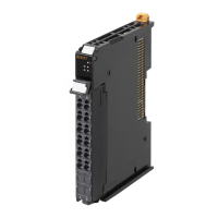
A-1-4 Digital Mixed I/O Units
A-1-4 Digital Mixed I/O Units
Description of Items on the Data Sheet of the DC Input/Transistor
Output Units
Item Description
Unit name The name of the Unit.
Model The model of the Unit.
Number of points The number of input and output points provided by the Unit.
External connection terminals The type of terminal block and connector that is used for connecting the Unit.
I/O refreshing method The I/O refreshing methods that are used by the Unit. Free-Run refreshing and syn-
chronous I/O refreshing are available.
Output sec-
tion (CN1)
Internal I/O common The polarity of the output devices that are connected to the Unit. NPN connection
and PNP connection are available.
Rated voltage The rated output voltage of the Unit.
Operating load volt-
age range
The output load voltage range of the Unit.
Maximum value of
load current
The maximum output load current of the Unit. The specifications for each output
point and for the Unit are described.
Maximum inrush cur-
rent
The maximum allowable inrush current of the Unit. Any inrush current from an exter-
nal connection load must be kept to or below this value.
Leakage current The leakage current when the output of the Unit is OFF.
Residual voltage The residual voltage when the output of the Unit is ON.
ON/OFF response
time
The delay time for which data in the internal circuit is reflected in the state of output
elements of the Unit. It is described according to the ON/OFF sequence.
Input sec-
tion (CN2)
Internal I/O common The polarity of the input devices that are connected to the Unit. NPN connection and
PNP connection are available.
Rated input voltage The rated input voltage and range of the Unit.
Input current The input current at the rated voltage of the Unit.
ON voltage/ON current The input voltage in which the Unit input turns ON, and corresponding input current.
OFF voltage/OFF cur-
rent
The input voltage in which the Unit input turns OFF, and corresponding input current.
ON/OFF response
time
The delay time for which the status change of the input terminals reaches the inter-
nal circuit of the Unit. The input filter time below is not included. It is described
according to the ON/OFF sequence.
Input filter time The filter time when the status of the internal circuit is read as the data to the internal
of the Unit. It is same for both ON/OFF. The filter time to be set by the Support Soft-
ware is described.
Indicators The type of indicators on the Unit and the layout of those indicators.
Dimensions The dimensions of the Unit. They are described as W x H x D. The unit is "mm".
Isolation method The isolation method of the I/O circuits and internal circuit of the Unit.
Insulation resistance The insulation resistance between the I/O circuits and internal circuit of the Unit.
Dielectric strength The dielectric strength between the I/O circuits and internal circuit of the Unit.
I/O power supply method The method for supplying I/O power to the Unit. The supply method is determined
for each Unit. The power is supplied from the NX bus or the external source.
Current capacity of I/O power supply
terminal
The current capacity of the I/O power supply terminals (IOV/IOG) of the Unit. Do not
exceed this value when supplying the I/O power to the connected external devices.
NX Unit power consumption The power consumption of the NX Unit power supply of the Unit.
Current consumption from I/O power
supply
The current consumption from I/O power supply of the Unit. The load current of any
external connection load, input current, and current consumption of any connected
external devices are not included.
Weight The weight of the Unit.
Circuit layout The circuit layout of the I/O circuits of the Unit.
Installation orientation and restric-
tions
The installation orientation of the Slave Terminal including the Unit, and the details of
restrictions on the specifications due to the installation orientation.
 Loading...