Appendices
A - 68
NX-series Digital I/O Unit User’s Manual (W521)
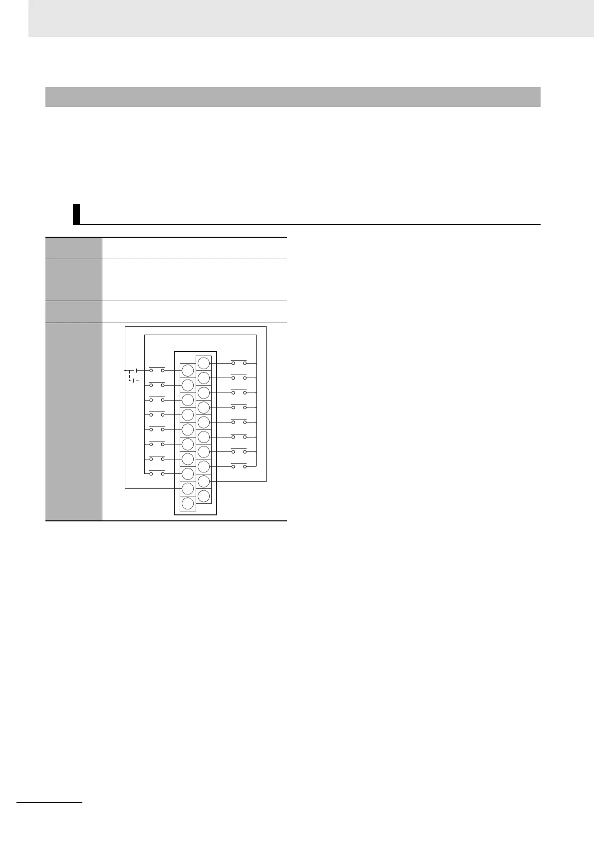
The applicable terminals on the Connector-Terminal Block Conversion Unit and external connection
diagrams are provided below for Digital I/O Unit connections to Connector-Terminal Block Conversion
Units.
In the connection diagrams here, 1 word consists of 16 points of the I/O terminals and the first word is
called Wd m.
Note 1. The COM terminals are internally connected
inside the Unit, but they must all be wired.
A-3-3 Connector-Terminal Block Conversion Unit Connection Diagrams
Inputs
Digital I/O
Unit
NX-ID5142-5
Connec-
tor-Terminal
Block Con-
version Unit
XW2D-20G6
Connecting
Cable
XW2Z-
X
Connection
diagram
A10
A1
A2
A3
A4
A5
A6
A7
A8
A9
B10
B1
B2
B3
B4
B5
B6
B7
B8
B9
09
08
NC
10
11
12
13
14
15
COM
01
00
NC
02
03
04
05
06
07
COM
24
VDC
 Loading...