Appendices
A - 74
NX-series Digital I/O Unit User’s Manual (W521)
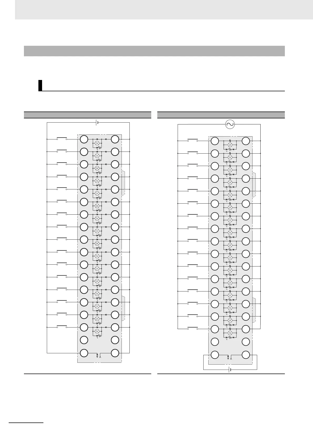
Connection examples and internal connection diagrams for I/O Relay Terminals connected to Digital I/O
Units are shown below.
G7TC I/O Relay Terminals
Note 1. Inputs to the Input Units and I/O Relay Terminals
use isolated contacts. “00” to “15” are the input bit
numbers for the Input Unit and the I/O Relay Ter-
minal.
2. Use the G78-04 short bar to short to the common
terminal.
Note 1. Inputs to the Input Units and I/O Relay Terminals
use isolated contacts. “00” to “15” are the input bit
numbers for the Input Unit and the I/O Relay Ter-
minal.
2. Use the G78-04 short bar to short to the common
terminal.
A-3-4 Connection Diagrams for I/O Relay Terminals
Inputs
G7TC-ID16
Input Unit
G7TC
15
14
13
12
11
10
9
8
7
6
5
4
3
2
1
0
C15
C14
C13
C12
C11
C10
C9
C8
C7
C6
C5
C4
C3
C2
C1
C0
NC NC
15
14
13
12
11
10
09
08
07
06
05
04
03
02
01
00
Relay side
+
−
G7TC-IA16
Input Unit
15
14
13
12
11
10
9
8
7
6
5
4
3
2
1
0
NC
C15
C14
C13
C12
C11
C10
C9
C8
C7
C6
C5
C4
C3
C2
C1
C0
NC
14
13
12
11
10
09
08
07
06
05
04
03
02
01
00
15
G7TC
Relay side
+
−
 Loading...