1021
Serial Communications Instructions Section 3-24
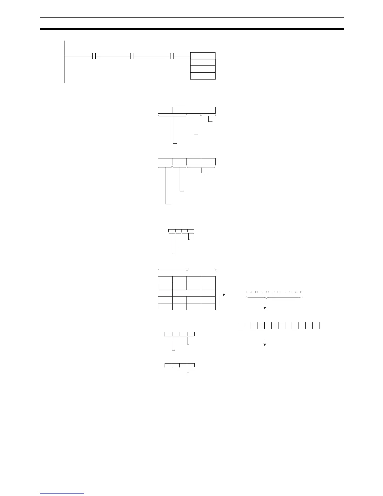
3-24-7 CHANGE SERIAL PORT SETUP: STUP(237)
Purpose Changes the communications parameters of a serial port on the CPU Unit,
Serial Communications Board (CS Series only), or Serial Communications
Unit (CPU Bus Unit). STUP(237) thus enables the protocol mode to be
changed during PLC operation.
RXDU
D00100
D00200
&10
155906
A20203
D
C
N
000000
C: D00200
0
0 7 815
0
11 12
3
0
Serial Communications Unit's unit address
(CPU Bus Unit's unit address)
12: Unit address + 10 hex
7 815
1
11 12
0 1
4 3
Always 0
0: No RS and ER signal control
1 2
4 3
3: Communications port No. 3
Communication port No. specifier (internal logic port)
1: Serial port No. 1
Serial Communications Unit's serial port specifier
D: D00100
0 7 815
4 1 2
Most significant bytes Least significant bytes
D00101
8 5 6
D00102
A
B
1 2 3 4 5 6 7 8 A B C D E F G H I J K L
10 bytes
3412ST 56 78 AB CD
ST: Start code (e.g., 02 hex)
ED: End code (e.g., 03 hex)
Data received
D
3
7
C
H E F
L I J
G
K
D00103
D00104
EF GH IJ KL ED
C+1: D00201
C+1
3
0
88: 80 + (04_Unit No. 2)
7 815
0
11 12
8 8
4 3
3: Communications port No. 3
Communications port No. specifier (internal logic port)
0: Directly specified serial port unit address
Note: Allocated DM Area Settings
• Start code/end code
D30204:
0
End code (e.g., 03 hex)
7 815
2
11 12
0 3
4 3
Start code (e.g., 02 hex)
0
• Start code/end code specifier
D30205:
0 7 815
1
11 12
4 3
1
End code specifier
1: Use end code
00: Unlimited (256 bytes max.)
1: Least significant byte to most significant byte
RS and ER signal control
Serial Communications Unit's serial port unit address specifier
Number of receive data bytes
Start code specifier
1: Use start code
Communications
Port Enabled
Flag
Reception
Completed
Flag
Note: The Serial Communications Unit's serial port unit address can
also be directly specified in C+1.
Received in
specified
order:
Start and end codes added
according to setting in PC Setup
 Loading...


