288
Timer and Counter Instructions Section 3-6
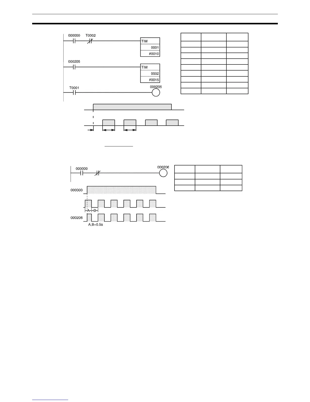
Clock Pulse
The desired execution condition can be combined with a clock pulse to mimic
the clock pulse (0.1 s, 0.2 s, or 1.0 s).
3-6-13 Indirect Addressing of Timer/Counter Numbers
Timer and counter numbers can be indirectly addressed using Index Regis-
ters. When Index Registers will be used for indirect addressing, use
MOVRW(561) (MOVE TIMER/COUNTER PV TO REGISTER) to set the PLC
memory address of the desired timer or counter’s PV to the desired Index
Register.
The following timers and counters can be indirectly addressed using Index
Registers: TIM, TIMX(550), TIMH(015), TIMHX(551), TTIM(087),
TTIMX(555), TMHH(540), TMHHX(552), TIMW(813), TIMWX(816),
TMHW(815), TMHWX(817), CNT, CNTX(546), CNTR(012), CNTRX(548),
CNTW(814), and CNTWX(818). (These are the timers and counters that use
timer and counter numbers.)
The timer or counter instruction will not be executed if the PLC memory
address in the specified Index Register is not the address of a timer or counter
PV.
Using Index Registers to indirectly address timers and counters can reduce
the size of the program and increase flexibility. For example, common subrou-
tines can be created.
Example The following example shows a program section that uses indirect addressing
to define and start 100 timers with SVs contained in D00100 through D00199.
CIO 000000
CIO 000205
1.5 s1.0 s 1.5 s1.0 s
000000 LD 000000
000001 AND T0002
000002 TIM 0001
#0010
000003 LD 000205
000004 TIM 0002
#0015
000005 LD T0001
000006 OUT 000205
Instruction OperandsAddress
000000 LD 000000
000001 AND 1s
000002 OUT 000206
Instruction OperandsAddress
1-s clock pulse
1-s clock
pulse
 Loading...


