206
Sequence Control Instructions Section 3-5
the same time as it writes the status of the execution condition (power flow) to
the specified output bit in I/O memory.
When OUTB(534) is programmed between IL(002) and ILC(003), the speci-
fied bit will be turned OFF if the program section is interlocked. (This is the
same as an OUT instruction in an interlocked program section.)
When a word is specified for the bit number (N), only bits 00 to 03 of N are
used. For example, if N contains FFFA hex, OUTB(534) will control bit 10 of
word D.
Note Difference between SETB(532)/RSTB(533) and OUTB(534)
For OUTB(534), the operand bit is turned ON when the input condition turns
ON and is turned OFF when the input condition turns OFF. For SETB(532)
and RSTB(533), the operand bit turns ON or OFF, respectively, when the input
condition turns ON and the operand bit does not change when the input con-
dition turns OFF.
Example
Note Precaution for Index Registers
OUTB(534) is executed even when the input condition turns OFF. Be particu-
larly careful when programming OUT using an indirect index register address.
3-5 Sequence Control Instructions
3-5-1 END: END(001)
Purpose Indicates the end of a program.
Ladder Symbol
Variations
Applicable Program Areas
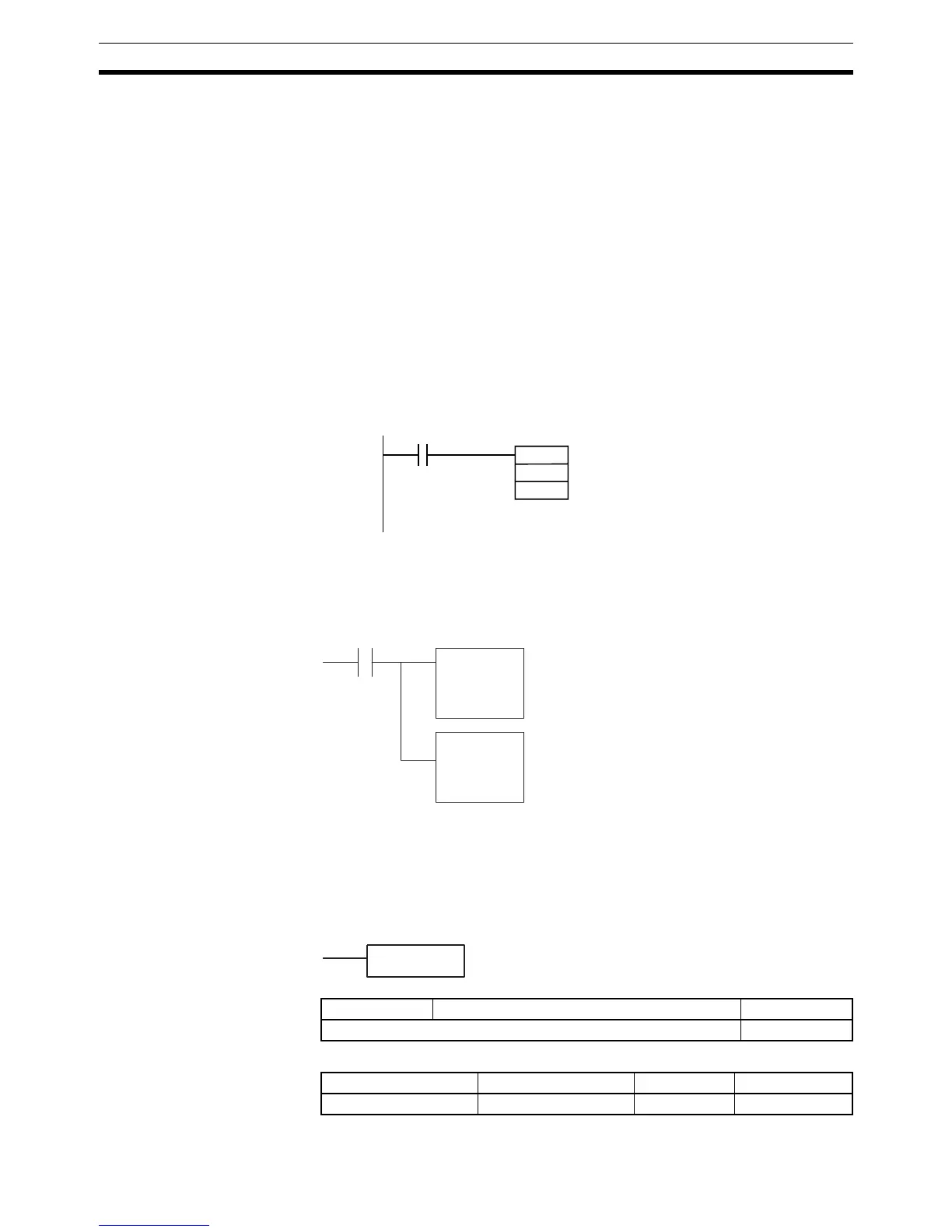
000000
OUTB
D00000
&10
Bit 10 of D00000 is turned OFF
when CIO 000000 is OFF.
MOVR
D100
IR0
Input condition
OUTB
,IR0
&15
When the input condition is OFF,
MOVR(560) is not executed, but
OUTB(534) is executed for the address
stored in the index register.
END(001)
Variations Executed Each Cycle for ON Condition END(001)
Immediate Refreshing Specification Not supported
Block program areas Step program areas Subroutines Interrupt tasks
Not allowed Not allowed Not allowed OK
 Loading...


