1076
Network Instructions Section 3-25
Description Sends the “read information/status” explicit message command (stored in
words S+1 to S+3) to the node address specified in S, via the Communica-
tions Unit with the FINS unit address specified in bits 00 to 07 of C+1.
When the response to the explicit message is received, the response’s ser-
vice data (data following the service code) is stored in the range of words
beginning at D+1.
The number of bytes of received data indicated in D is the number of bytes of
service data. (For example, if there is 1 byte of service data, D will contains
0001 hex. D will contain 0001 hex regardless of the byte order setting, i.e.,
whether the byte is stored in the rightmost or leftmost byte of D.)
The setting in bits 12 to 15 of C+1 (0 or 8 hex) determines the byte-order of
the service data stored at S+6 and D+3.
• Storing Data from the Leftmost Byte
Set bits 12 to 15 of C+1 to 0 hex.
Counter Area C0000 to C4092 C0000 to C4095 C0000 to C4092
DM Area D00000 to
D32764
D00000 to
D32767
D00000 to
D32764
EM Area without bank E00000 to
E32764
E00000 to
E32767
E00000 to
E32764
EM Area with bank En_00000 to
En_32764
(n = 0 to C)
En_00000 to
En_32767
(n = 0 to C)
En_00000 to
En_32764
(n = 0 to C)
Indirect DM/EM
addresses in binary
@ D00000 to @ D32767
@ E00000 to @ E32767
@ En_00000 to @ En_32767 (n = 0 to C)
Indirect DM/EM
addresses in BCD
*D00000 to *D32767
*E00000 to *E32767
*En_00000 to *En_32767 (n = 0 to C)
Constants ---
Data Registers ---
Index Registers ---
Indirect addressing using
Index Registers
,IR0 to ,IR15
–2048 to +2047, IR0 to –2048 to +2047, IR15
DR0 to DR15, IR0 to IR15
,IR0+(++) to ,IR15+(++)
,–(– –)IR0 to, –(– –)IR15
Area S D C
A
15
AD+1
D+2
B
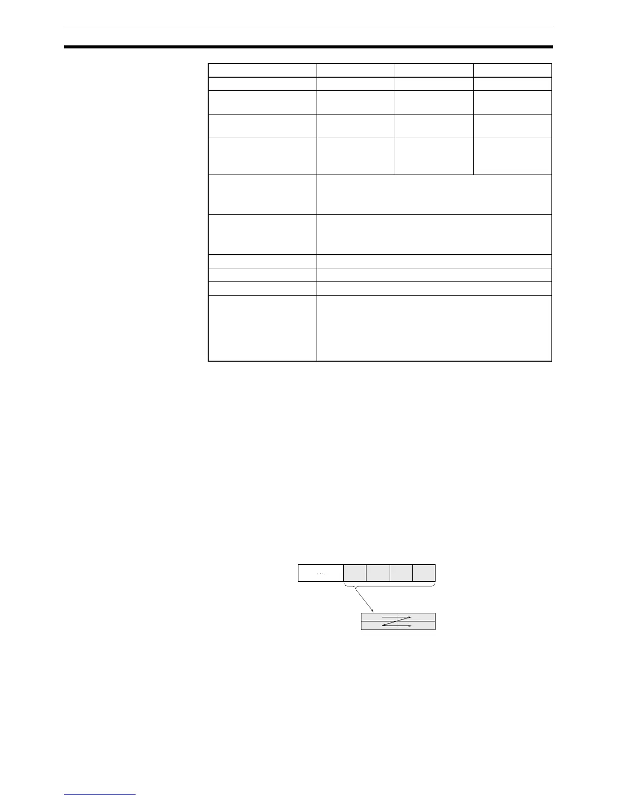
CD
08 07 00
BCD
Frame (order of data in line)
Stored from leftmost byte.
Note: A, B, C, and D represent bytes of data.
Data
area
 Loading...


