782
Data Control Instructions Section 3-18
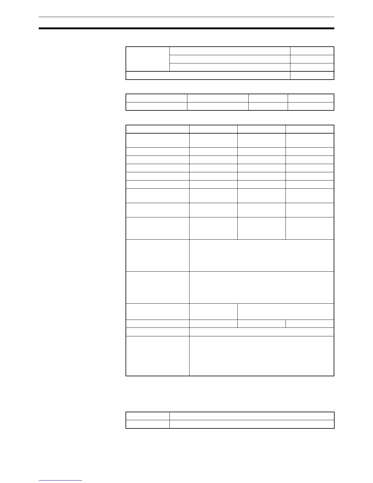
Variations
Applicable Program Areas
Operand Specifications
Description When the execution condition is ON, BAND(681) controls output data accord-
ing to whether or not the specified input data (signed 16-bit binary) is within
the upper and lower limits (dead band). The contents of words C and C+1 are
as follows:
C and C+1 must have the same area classification.
Variations Executed Each Cycle for ON Condition BAND(681)
Executed Once for Upward Differentiation @BAND(681)
Executed Once for Downward Differentiation Not supported.
Immediate Refreshing Specification Not supported.
Block program areas Step program areas Subroutines Interrupt tasks
OK OK OK OK
Area S C D
CIO Area CIO 0000 to CIO
6143
CIO 0000 to CIO
6142
CIO 0000 to CIO
6143
Work Area W000 to W511 W000 to W510 W000 to W511
Holding Bit Area H000 to H511 H000 to H510 H000 to H511
Auxiliary Bit Area A000 to A959 A000 to A958 A448 to A959
Timer Area T0000 to T4095 T0000 to T4094 T0000 to T4095
Counter Area C0000 to C4095 C0000 to C4094 C0000 to C4095
DM Area D00000 to
D32767
D00000 to
D32766
D00000 to
D32767
EM Area without bank E00000 to
E32767
E00000 to
E32766
E00000 to
E32767
EM Area with bank En_00000 to
En_32767
(n = 0 to C)
En_00000 to
En_32766
(n = 0 to C)
En_00000 to
En_32767
(n = 0 to C)
Indirect DM/EM
addresses in binary
@ D00000 to @ D32767
@ E00000 to @ E32767
@ En_00000 to @ En_32767
(n = 0 to C)
Indirect DM/EM
addresses in BCD
*D00000 to *D32767
*E00000 to *E32767
*En_00000 to *En_32767
(n = 0 to C)
Constants #0000 to #FFFF
(binary)
---
Data Registers DR0 to DR15 --- DR0 to DR15
Index Registers ---
Indirect addressing
using Index Registers
,IR0 to ,IR15
–2048 to +2047 ,IR0 to –2048 to +2047 ,IR15
DR0 to DR15, IR0 to IR15
,IR0+(++) to ,IR15+(++)
,–(– –)IR0 to, –(– –)IR15
C Lower limit data (dead band lower limit)
C+1 Upper limit data (dead band upper limit)