876
High-speed Counter/Pulse Output Instructions Section 3-21
Description PRV2(883) converts the pulse frequency input from high-speed counter 0,
according to the conversion method specified in C1 and the pulses/revolution
coefficient specified in C2, and outputs the result to D and D+1.
Select one of the following conversion methods by setting C1 to 0000 hex or
0001 hex.
Converting Frequency to Rotation Speed (C1 = 0
@*0 hex)
If C1 is 0@*0 hex, PRV2(883) calculates the rotation speed (r/min) from the
frequency data and pulses/revolution setting. The second digit of C (@) speci-
fies the units and the third digit (*) specifies the frequency calculation method.
1. Rotation Speed Units
• Rotation Speed Units = r/min
When the second digit of C (@) is 0, PRV2(883) calculates the rotation
speed in r/min from the frequency data and pulses/revolution setting.
Rotation speed (r/min) = (Frequency
÷ Pulses/revolution) × 60
• Rotation Speed Units = r/s (CJM1 CPU Unit Ver. 3.0 or later only)
When the second digit of C (@) is 1, PRV2(883) calculates the rotation
speed in r/s from the frequency data and pulses/revolution setting.
Rotation speed (r/s) = Frequency
÷ Pulses/revolution
• Rotation Speed Units = r/h (CJM1 CPU Unit Ver. 3.0 or later only)
When the second digit of C (@) is 2, PRV2(883) calculates the rotation
speed in r/h from the frequency data and pulses/revolution setting.
Rotation speed (r/h) = (Frequency
÷ Pulses/revolution) × 60 × 60
• Range of Conversion Results
• Counter input method: Any method besides 4
× differential phase mode
Conversion result = 00000000 to 000186A0 hex (0 to 100,000)
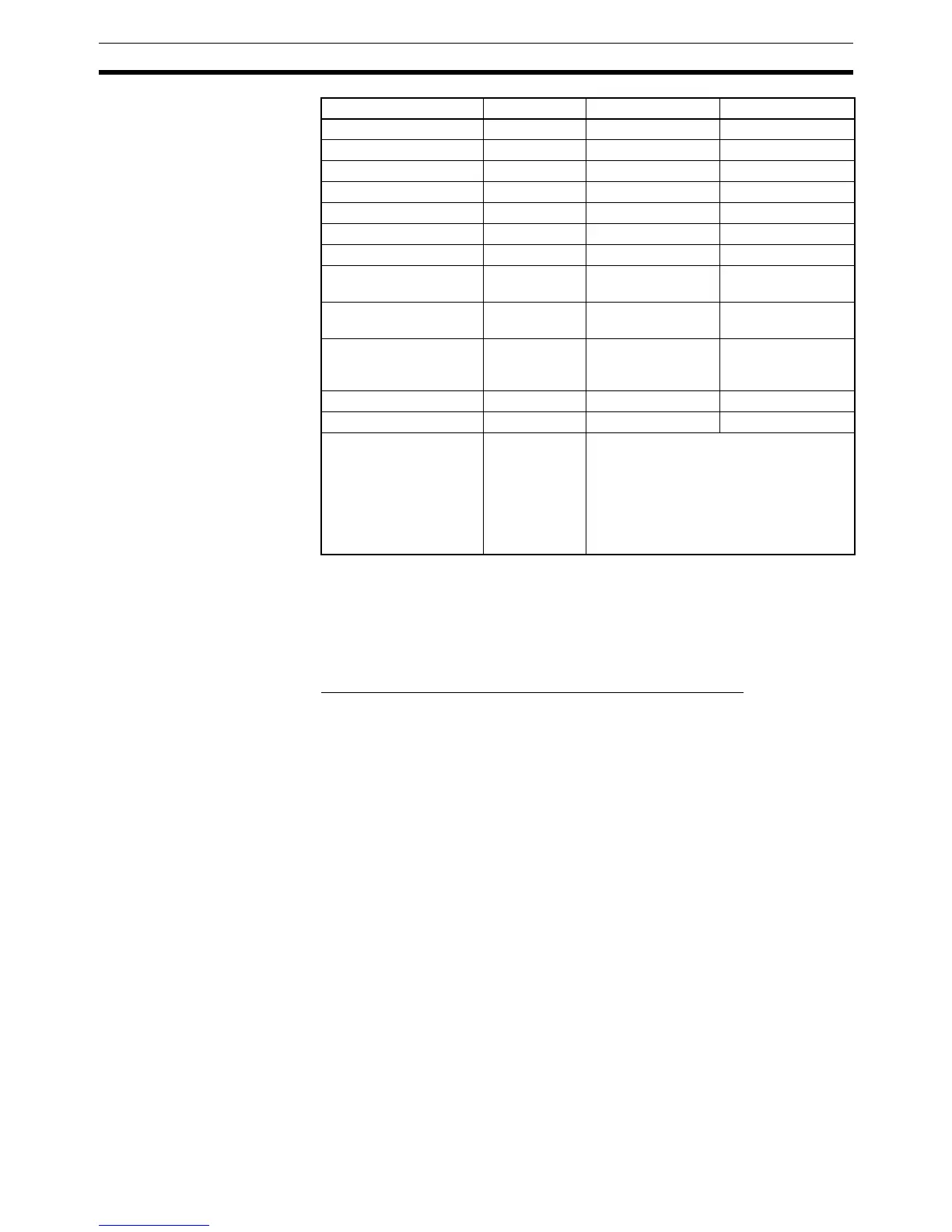
Holding Bit Area --- H000 to H511 H000 to H510
Auxiliary Bit Area --- A448 to A959 A448 to A958
Timer Area --- T0000 to T4095 T0000 to T4094
Counter Area --- C0000 to C4095 C0000 to C4094
DM Area --- D00000 to D32767 D00000 to D32766
EM Area without bank --- --- ---
EM Area with bank --- --- ---
Indirect DM/EM
addresses in binary
--- @ D00000 to @
D32767
@ D00000 to @
D32767
Indirect DM/EM
addresses in BCD
--- *D00000 to
*D32767
*D00000 to
*D32767
Constants See descrip-
tion of oper-
and.
--- ---
Data Registers --- --- ---
Index Registers --- --- ---
Indirect addressing
using Index Registers
--- ,IR0 to ,IR15
–2048 to +2047 ,IR0 to
–2048 to +2047 ,IR15
DR0 to DR15, IR0 to IR15
,IR0+(++) to ,IR15+(++)
,–(– –)IR0 to, –(– –)IR15
Area C1 C2 D
 Loading...


