2017-04
14
Absolute Rotary Encoder
Installation of Photoelectric Absolute Rotary Encoder
5 Installation of Photoelectric Absolute Rotary Encoder
The following chapter describes all aspects helpful for installation of photoelectric absolute
rotary encoders with bus cover. Depending on the rotary encoder model there are the following
connection variants:
■
Rotary encoder with bus cover equipped with cable glands
■
Rotary encoder with bus cover equipped with a cable exit
■
Rotary encoder with bus cover equipped with one or two M12x1 connectors, 5-pin
Bus cover features like node number adressing, baud rate setting and activation of termination
resistor are identical for all these variants.
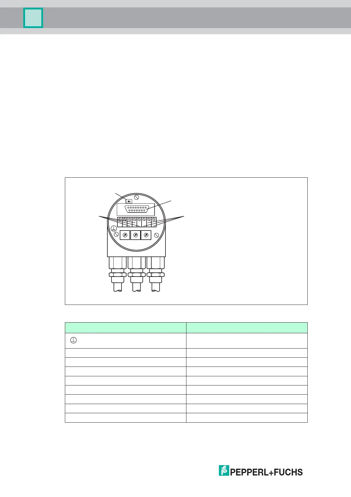
5.1 Signal Assignment of Terminal Block
The rotary encoder is connected with two or three cables depending on whether the power
supply is integrated into the bus cable or connected separately. If the power supply is
integrated into the bus cable, one of the cable glands can be fitted with a plug. The cable
glands are suitable for cable diameters from 6.5 up to 9 mm.
Figure 5.1
Te rm i na l Description
Ground
+ 24 V Supply Voltage
- 0 V Supply Voltage
G CAN Ground
L CAN Low (Bus In)
H CAN High (Bus In)
G* CAN Ground
L* CAN Low (Bus Out)
H* CAN High (Bus Out)
Table 5.1 * are not connected, if terminator is ON
ON
T
G
H
-+
G
x10Bd
x1
LLH
8
7
2
6
5
4
3
0
9 1
8
7
2
6
5
4
3
0
9 1
8
7
2
6
5
4
3
0
9 1
R
Te r m i n a t o r
Bus In
Bus Out
RS 485 Interface
 Loading...