Absolute Rotary Encoder
Installation of Magnetic Absolute Rotary Encoder
2017-04
21
6 Installation of Magnetic Absolute Rotary Encoder
The following chapter describes all aspects helpful for installation of magnetic absolute rotary
encoders. Depending on the rotary encoder model there are the following connection variants:
■
Rotary encoder with a cable exit
■
Rotary encoder with two M12x1 connectors, 5-pin
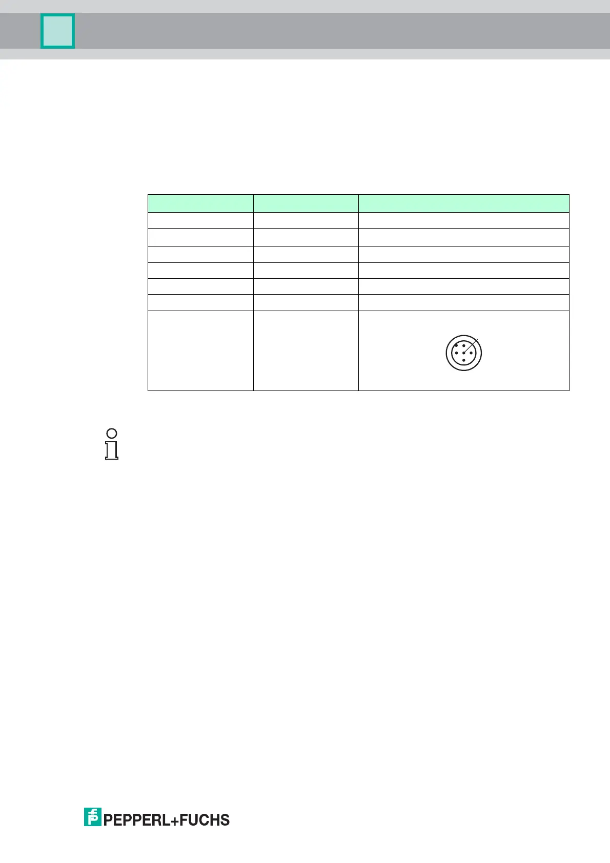
6.1 Signal Assignment of Connector and Cable Variants
6.2 Activation of Terminator
If the rotary encoder is connected at the end or beginning of the bus using of the internal
terminator is possible by parameterization of SDO object "3002 h" The internal terminator is
acitvated by writing "01 h" into this object.
6.3 Setting of Node Number and Baud Rate
Setting of the node number and baud rate has to be done by parameterization of the relevant
SDO objects or via LSS. Some absolute rotary encoders are provided with auto baud detection
(see relevant datasheet).
Default values are:
■
Baud rate 125 kBaud
■
Node number 32 decimal (20 h)
Setting Node Number via SDO Objects
The node number has to be adjusted via SDO objects. To set the node number, object 3000h
has to be written. For further information regard chapter "Object Descriptions".
Setting Baud Rate via SDO Objects
The baud rate has to be adjusted via SDO objects, if auto baud feature is not activated or is not
possible to use because of network start-up behavior. To set baud rate object 3001h has to be
written. For further information regard chapter "Object Descriptions".
Signal Wire end 5-pin, M12 x 1 connector
CAN GND green 1
+U
b
red 2
GND yellow 3
CAN-High white 4
CAN-Low brown 5
Shielding Shielding Housing
Pinout
Note!
The magnetic absolute rotary encoder is equipped with an internal terminator, which can be
used as a line termination. Be aware, that the terminator is only activated, when the encoder is
powered, because the microcontroller is internally needed to switch on the terminator.
 Loading...