2017-04
16
Absolute Rotary Encoder
Installation of Photoelectric Absolute Rotary Encoder
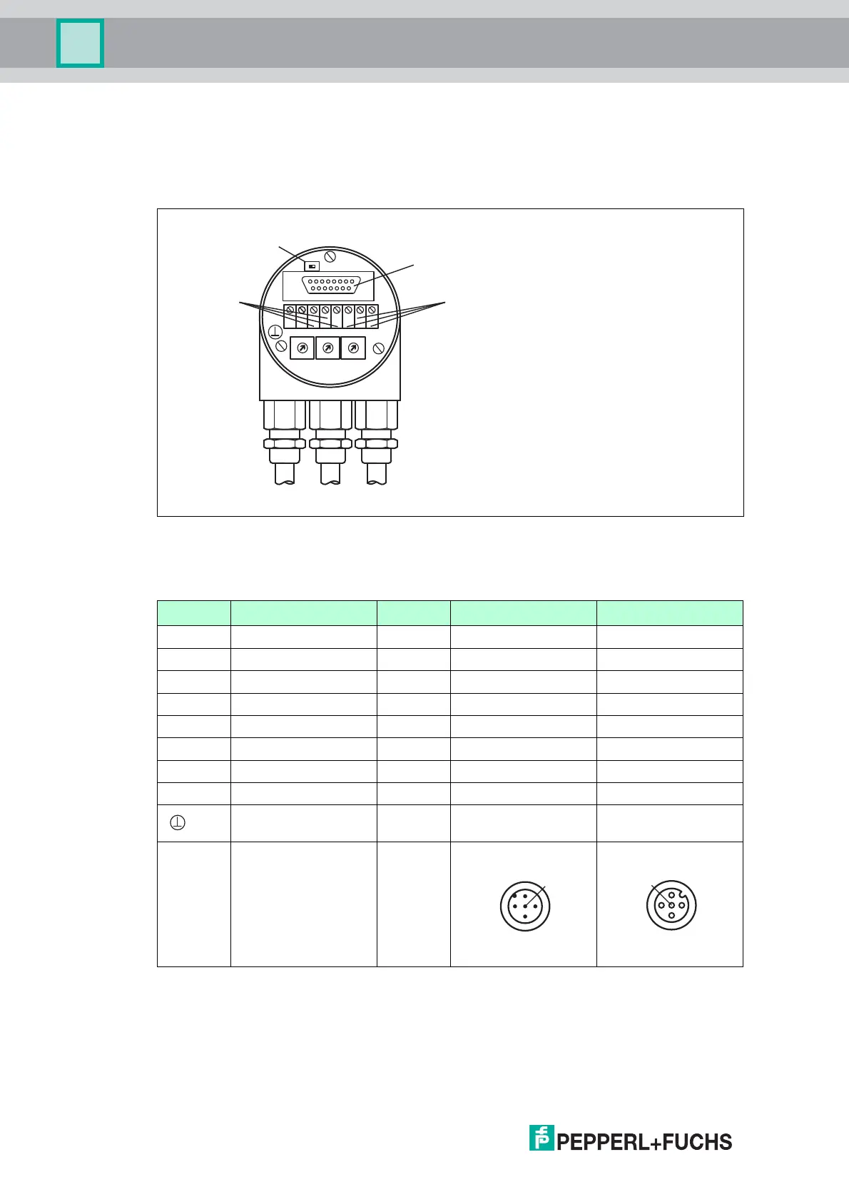
5.2 Signal Assignment of Connector and Cable Variants
The rotary encoders with cable- and connector-exit were designed in accordance to CiA
normative DR303-1 cabeling and connector pin assignment. They also have a removable bus
cover with all possibilities to set node number, baud rate and acitvate terminator.
Figure 5.2
The following table shows an assignment of the different connecting types (cable, connectors)
to the terminals of the bus cover.
Te rm i na l Description Cable M12 plug, 5-pin M12 socket, 5-pin
(-) - Power supply 1 3 3
(+) + Power supply 2 2 2
L CAN Low (Bus In) 3 5
H CAN High (Bus In) 4 4
G CAN Ground 5 1
L* CAN Low (Bus Out) 6 5
H* CAN High (Bus Out) 7 4
G* CAN Ground 8 1
Ground connection of
encoder housing
green/
yellow
Table 5.2 * are not connected, if terminator is ON
ON
T
G
H
-+
G
x10Bd
x1
LLH
8
7
2
6
5
4
3
0
9 1
8
7
2
6
5
4
3
0
9 1
8
7
2
6
5
4
3
0
9 1
R
Te r m i n a t o r
Bus In
Bus Out
RS 485 Interface
 Loading...