Absolute Rotary Encoder
Installation of Photoelectric Absolute Rotary Encoder
2017-04
17
5.3 Activation of the Terminator
There is a terminator provided in the bus cover, which must be used as a line termination on the
last device. The terminator is switched on when the switch is in the "ON position" (see figure
before).
5.4 Installation Hints for Cabling
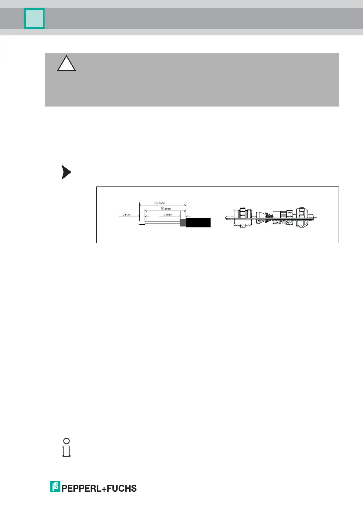
Cable Connection with Cable Gland
1. Remove screw, sealing and cone from the cable gland.
Figure 5.3
2. Remove 55 mm of the sheath and 50 mm of the shielding. About 5 mm of the wires should
be de-isolated.
3. Put screw and sealing on the cable.
4. The cone should be mounted under the shielding according to the figure before. Put the
whole cable into the cable gland and tighten the screw.
Minimization of Signal Interferences
Both the cable shielding and the metal housings of rotary encoders and subsequent
electronics have a shielding function. The housing must have the same potential and be
connected to the main signal ground over the machine chassis or by means of a separate
potential compensating line. Potential compensating lines should have a minimum cross
section of 6 mm
2
.
Do not lay signal cable in the direct vicinity of interference sources (air clearance > 100 mm (4
in.))
A minimum spacing of 200 mm (8 in.) to inductors is usually required, for example in switch-
mode power supplies.
Configure the signal lines for minimum length and avoid the use of intermediate terminals.
Shielded fieldbus cables shall be used! The shield must be grounded according to EMI rules!
In metal cable ducts, sufficient decoupling of signal lines from interference signal transmitting
cable can usually be achieved with a grounded partition.
5.5 Setting of Node Number and Baud Rate in the Bus Cover
Caution!
Activated bus termination separates "Bus in" and "Bus out".
Non-observance of separation of "Bus in" and "Bus out" causes interferences on the CANopen
bus.
If you activate the bus termination on the rotary encoder ensure that the rotary encoder is the
last CANopen bus participant in the bus line.
Note!
Setting of node number and baud rate has to be done via software if Bd rotary switch is set to 9.
SDO objects and Layer Setting Services (LSS) are provided for this purpose.
 Loading...