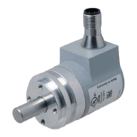
Absolute Rotary Encoder
Quick Start Guide
2017-04
23
7Quick Start Guide
Intention of this chapter is to help the user getting a magnetic or photoelectric absolute rotary
encoder very easy and fast to operate. The user is still responsible to configure the absolute
rotary encoder in the right way and reading the whole manual carefully.
With the following sequence a normal procedure is described to configure a device for
standard applications. It shall guide you roughly through this process.
7.1 Configure the Absolute Rotary Encoder for Integration into a CAN
Network
For this purpose you need to set up the node number and the baud rate first.
Depending on your absolute rotary encoder model there are different ways to do so.
■
Photoelectric absolute rotary encoder with bus cover: Setting is possible via BCD coded
rotary switches or if rotary switch Bd = 9 via SDO objects or Layer Setting Services (LSS).
■
Magnetic absolute rotary encoder: Default setting for node number is 32 decimal and
baud rate is 125 kBaud. If other settings are required setting is only possible via SDO
objects or Layer Setting Services (LSS). Some models have auto baud rate detection (see
relevant datasheet) which has to be checked if activated. If this feature is activated so only
node number has to be set.
First Steps of Configuration of a Magnetic Absolute Rotary Encoder
1. If the encoder has no active auto baud detection connect the encoder with a configuration
tool and set the baud rate to 125 kBd.
2. Power on the encoder.
You will see a boot up message in case of a trace tool is used. For devices equipped with
status LEDs a green colored LED is blinking to indicate the CAN state PRE-
OPERATIONAL.
3. If necessary activate the terminator of the encoder by writing "01h" into object "3002 h".
4. Continue by reading and writing data into the relevant following objects in this chapter.
First Steps of Configuration of a Photoelectric Absolute Rotary Encoder
1. Set the baud rate desired with rotary switch Bd (20 kBd factory default) and the node ad-
dress you need with rotary switches x10 and x1 (32 factory default) . If Bd = 9 connect the
encoder with a configuration tool and set the baud rate desired.
2. Power on the encoder.
You will see a boot up message in case of a trace tool is used. For devices equipped with
status LEDs a green colored LED is blinking to indicate the CAN state PRE-
OPERATIONAL.
Caution!
Check requirements of baud rate and node number of your network before configuration!
If your running network uses a different baud rate or the node number is already in use, then
you shall make a point-to-point connection to the encoder with a configuration tool to prevent a
crash of the different configured running network. If auto baud feature is used in the encoder it
simplifies installation.
Note!
In case you want to set baud rate and node number via SDO objects rotary switch Bd has to be
in position 9.

 Loading...