Adjustment
14 - 19
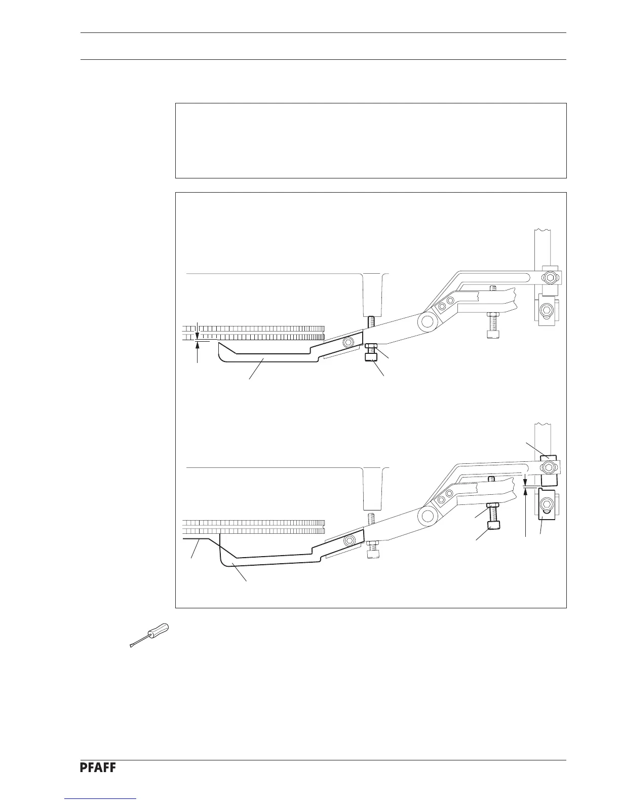
0.3 mm
0.5 mm
1
6
5
4
1
2
8
7
3
Fig. 14 - 18
● Bring the machine into its left buttonhole seam position.
● Loosen nut 5 and turn screw 6 in accordance with requirement 1.
● Tighten nut 5.
● Turn the control cam by turning the handwheel so that the sensing lever 1 is at the
highest point of trip 2.
● Loosen nut 7 and turn screw 8 in accordance with requirement 2.
● Tighten nut 7.
14.10 Sensing lever and catch lever
Requirement
1. With the machine in its left buttonhole seam position, there must be a clearance of
0.3 mm between the projection of the sensing lever 1 and the control cam.
2. When the sensing lever 1 is at the highest point of trip 2 there must be a clearance of
0.5 mm between the catches 3 and 4.
 Loading...