Adjustment
14 - 43
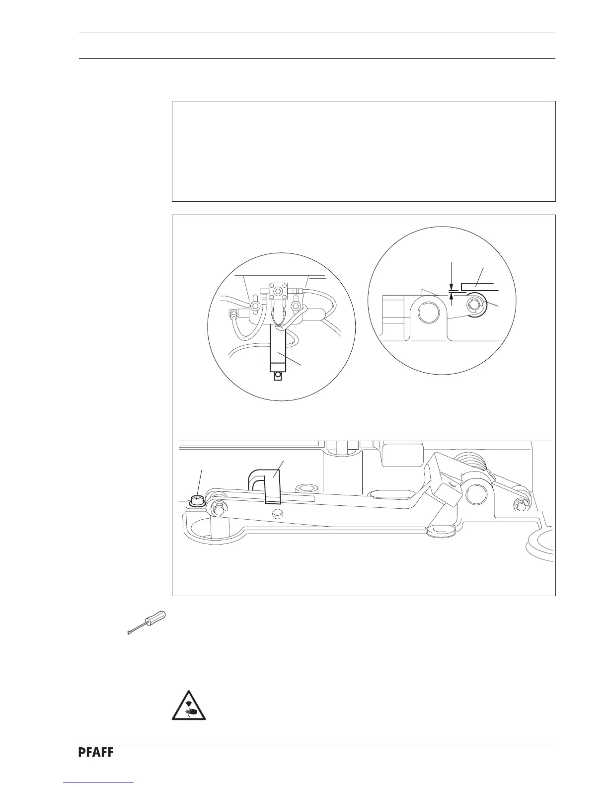
Fig. 14 - 41
0,5 mm
3
1
6
5
4
● Lay the machine head on its side.
● With the feed lifting cylinder 1 extended, loosen the screws 3.
● Move the angle bracket 4 in accordance with requirement 1.
● Tighten screws 3.
● Return the machine head to its upright position.
Danger of crushing between machine head and table top!
14.19 Feed lifting cylinder
Requirement
1. With the feed lifting cylinder 1 extended there must be a clearance of 0.5 mm between
the presser roller and the pressing surface of the lever 6.
2. With the feed lifting cylinder 1 retracted ( see fig. 14.42 ), the lever 2 of the work
clamp must be able to be lifted a little more.
3. With the feed lifting cylinder 1 retracted, the work clamp must rise 12.5 mm from the
feeder.
 Loading...