Adjustment
14 - 29
● Bring the machine to its program end position.
● Disengage the stop motion device.
● Manually push out the needle thread scissor.
● Mount the knife adjustment gauge 2 onto the knife carrier 3.
● Carefully push the knife bar 1 down with your finger and check that the knife adjustment
gauge 2 can enter the cutting slot 4.
● If not, proceed to chapter 14.12.07 Position of the knife carrier relative to the cutting
slot.
● Turn the handwheel until the switch function of the knife is carried out.
● Hold the thread monitor finger forwards.
● Turn the drive pulley in its direction of rotation until screw 5 becomes visible.
● Loosen screw 5 a little.
● Turn the drive pulley in its direction of rotation until the knife bar 1 is at its BDC.
● In this position the knife adjustment gauge 2 must rest on the needle plate 6 ( = 16.5
mm ).
● Tighten screw 5.
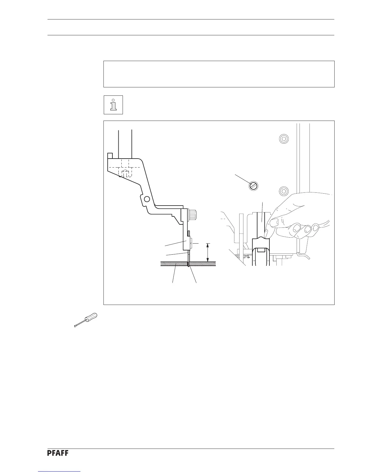
14.12.06 Knife bar height
Requirement
The height of the knife bar 1 must be adjusted with the aid of the knife adjustment
gauge 2.
Carry out this adjustment with a needle plate with a knife actuating hole
mounted.
Fig. 14 - 27
3
4
2
6
1
5
16.5 mm
 Loading...