2: The Control Panel
PIMA Electronic Systems
11
Ethernet socket. FORCE 32: available only for connecting to the
FORCE Manager software.
Technician keypad’s and local zone expander ZEL508 connector
Earth ground; use only with non-PIMA non-metal cases!
Telephone line; FORCE Lite: unavailable
Telephone set, fax, answering machine; FORCE Lite: unavailable
Backup battery, Red (+)/Black (-) cables
The Int. Siren, Relay, and Line/Set terminals are not assembled in the
FORCE Lite PCB, and the transformer’s voltage is 14.5VAC.
2.3.1 The bus
The bus is a serial communication channel, used for exchanging data between the control panel
and the peripherals. The protocol in use by the bus is ForceCom (PIMA proprietary).
Use four 0.5mm (24 Gauge (AWG)) wires for the bus. The maximum bus length is
500m, including all peripherals and keypads.
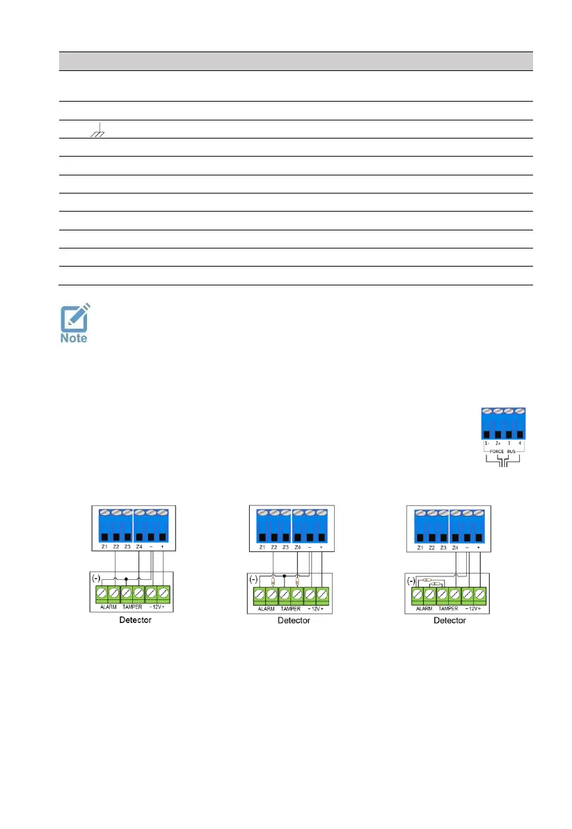
Connect the wires using the numbers 1-4, where terminal #1 on the control panel
connects to the same terminal on the peripheral, and so on.
2.3.2 Zone wiring
End Of Line resistor
 Loading...