FORCE Series Installation Guide
12 PIMA Electronic Systems
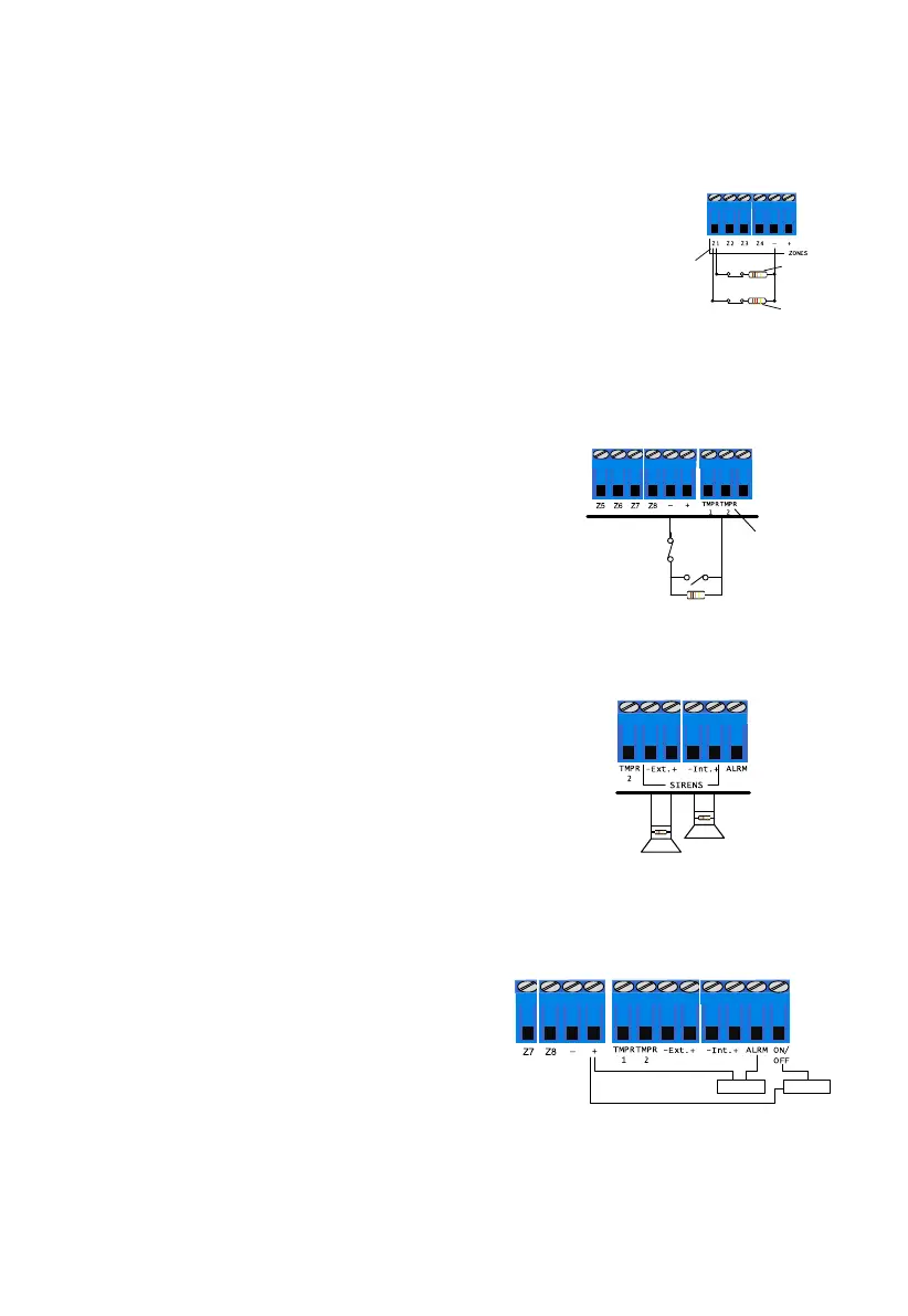
2.3.3 Zone doubling
Zone Doubling allows you to double the eight onboard zones to 16. All doubled zones must be
wired according to the diagram below.
In the diagram on the right (all values are for example only), the zone
using the 10KΩ resistor will be the first zone (lower number zone) and
the zone using the 5.1KΩ resistor will be the second zone (higher
number zone).
For example, Zone #1 input will serve Zone #1 (10KΩ) and Zone #9
(5.1KΩ), Zone #2 input will serve Zone #2 and zone #10, and so on.
2.4 Tamper switches
TMPR 1 & 2 are inputs for tamper switches in boxes, detectors, sirens, etc.
By default, the control panel’s box tamper is connected to TMPR 1 input.
To connect tampers, follow the next steps:
1. Connect one wire to the TMPR 1 or 2 terminals.
FORCE Lite/32: TMPR2 terminal is not available.
2. Connect the other wire to a (-) input.
3. Set the tampers parameters.
2.5 Wired sirens
Connect any DC siren (only) to the FORCE. To connect sirens, do the steps that follow:
1. Connect an internal siren to the SIRENS Int.
(internal) +/- terminals. FORCE Lite/32: the Int.
terminal is unavailable.
2. Connect an external siren to the SIRENS Ext.
(external) +/- terminals.
3. For EOL loop supervision, connect a 2KΩ resistor
between the siren’s wires, close or inside the
siren’s enclosure.
Figure 7. Sirens connection diagram
2.6 Alarm and On/Off outputs
The Alarm and On/Off are open drain outputs.
Connect devices (up to 10A) between the output
and the (+).
The Alarm output supplies ground when the
alarm is triggered (by default).
The On/Off output supplies ground on arming
the alarm system (by default).
Zone 1
(-)
Zone 9
10KW, 5%
5.1KW, 5%
Z1
Control Panel
Control Panel
TMPR 1-2
(-)
Tamper
Switch
Sensor
EOL (optional)
External
Siren
Internal
Siren

 Loading...