Force Security System - Installation Guide
18
Figure 17. TRV/TRU-100 connection diagram
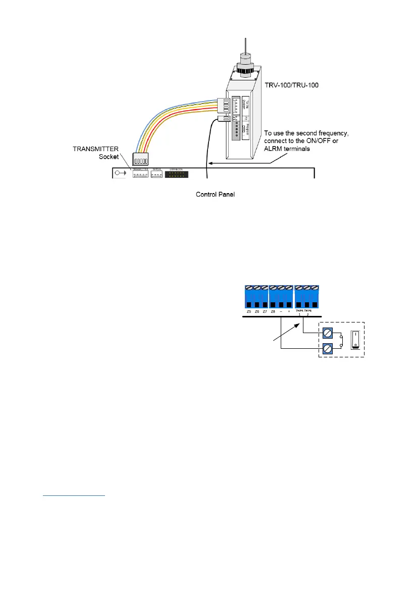
2.11 Connecting tamper switches
TMPR 1 & 2 serve as inputs for tamper switches in boxes, detectors, sirens, etc. The inputs are
set in the
Peripherals
Tampers & EOLs
menu (see section 5.2, on page 26).
By default, the control panel’s box tamper is connected to TMPR 1 input.
To connect tampers, follow the next steps:
1. Connect one wire to the TMPR 1 or 2 terminals.
2. Connect the other wire to a (-) input.
3. Set the tampers parameters.
2.12 Connecting keypads
2.12.1 Keypads installation guidelines
16 addressable keypads (max) numbered 1-16 (or un-addressable keypads with ID=0).
The ID numbers must be consecutive.
Keypad with ID=0 cannot be supervised, nor partitioned.
The ID number is set in the
Expanders
Keypads Setting
menu (see section 5.3, on
page 27).
2.12.2 LCD keypads, KLT/KLR500
Main features
Touch/rubber keys, 7-line LCD screen, 128x64 pixels display
4 operational LEDs
Interfaces with the BUS and uses PIMA proprietary protocol
Tamper switch protection
Control Panel
TMPR 1-2
Inputs
(-)
Tamper Zone
 Loading...