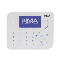
Force Security System - Installation Guide
46
3) Output Expanders: select an expander (press # or *) and an output, and
Activate/
Deactivate
it. To easily locate the expander, press
Activate Buzzer
and
Activate/Deactivate
the expander’s buzzer.
4) Keypad Buzzer:
Activate/Deactivate
the buzzer.
13.4 Power Diagnostics
Tests & Diagnostics
Power Diagnostics
The
Power Diagnostics
menu includes the following sub-menus, for viewing the control panel
and peripherals’ voltage and current status.
1) Zone Expanders: select
Local
or
Remote Expanders
and view the card’s voltage and
current.
2) Keypads: select a keypad (press # or *) and see its current voltage and current.
3) Output Expanders: select an expander (press # or *) and see its voltage and current.
4) Battery Voltage: the backup battery’s voltage status.
5) Panel Current: the control panel and the peripherals’ current consumption. Note that
PS
on
the display indicates that the peripheral is powered by a local power supply and so its
current is not pulled from the control panel.
13.5 Communication Tests
The FORCE allows you to test each CMS defined communication path - telephone number, URL
etc., by generating a Test report. During the test the display shows the online communication
process - dialing, connecting, sending, etc.
13.6 Communications Monitor
Select any communication path and view the current data exchange.

 Loading...