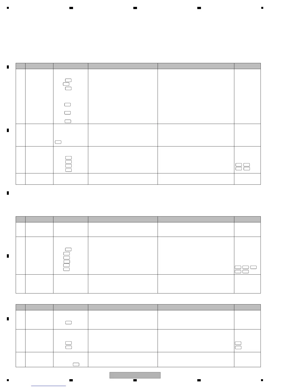
[5] Indicator (FL/LED) not lit
[5-1] The FL does not light.
SUB UCOM (IC6601) controls the FL/LED.
MAIN_CPU controls only LFO FORM (WAKE UP) button LED and EFFECT ON/OFF button LED.
Driver power to the FL is supplied within the MAIN Assy.
1 Power failure
PNLA Assy
V6601
24 pin
1 pin
25 pin
MAIN Assy
IC1407 V+3R3D
Block
IC1405 V+5D
Block
IC1401 V+34D
Block
Check for the voltage of the FL (V+3R3D_
PA/ V+5D_LED_PA/V+34D_PA).
If no loose connection is detected with the FL of
the PNLA Assy but power voltage is not detected,
check the mounting status of the DC-DC converter
IC and peripheral parts for each voltage point of
the MAIN Assy.
If an error is detected, repair the defective parts.
4.3 POWER
BLOCK DIAGRAM
5.3 INFORMATION
ON POWER
DIAGNOSTICS
2
Filament
voltage error
of the FL
PNLA Assy
Voltage between pins
1 to 32 of V6601
Check that the FL filament voltage is
2.3 V ± 20%.
If the voltage is outside the normal range, a bias
circuit error of the FL may be suspected.
Check the mounting status of Q6601, Q6602, and
peripheral parts. If there is no problem, Q6601 or
Q6602 may be defective. Replace them.
—
3 Signal errors
PNLA Assy
V6601
22 pin
21 pin
23 pin
24 pin
Check for the output signal of the FL communication
line and the cable connection status in the PNLA Assy.
• FL_SCK
• FL_TXD
• FL_LAT
• FL_BK
If no signal is output, check for the mounting
status of SUB UCOM (IC6601).
If there is no problem, the port may be defective.
Replace it.
If soldering is improper, resolder it.
4 Defective FL PNLA Assy
If the symptom persists after the above
corrections.
FL may be defective.
Replace it.
—
[6] X-PAD
SUB UCOM (IC6601) controls the X-PAD.
[6-1] Pressing on the JOG dial not be detected
1
Loose
connection
PNLA Assy
CDCB Assy
Check for loose connection on the signal
line from the power source and SUB UCOM
(IC6601) to the touch sensor IC (IC3601).
If any connection on the power or signal line is
improper, correct it.
2 Signal errors
Loose
connection
Signal errors
PNLA Assy
CN6601
10 pin
5 pin
8 pin
7 pin
3 pin
2 pin
Check for input and output signals of the communi-
cation line of the touch sensor IC in the PNLA Assy
when power is supplied and the unit is turned on.
• V+3R3 (power)
• RBC_SCK
• RBC_SI
• RBC_SO
• RBC_CS
• RBC_INT
If there is no signal when the unit is turned on,
check the mounting status of SUB UCOM
(IC6601).
If there is no problem, the port may be defective.
Replace it.
4.3 POWER
BLOCK DIAGRAM
5.3 INFORMATION
ON POWER
DIAGNOSTICS
10.41 WAVEFORMS
PNLA ASSY
3
Touch sensor IC
defective
PNLA Assy
(the same points
checked in No.2)
Check that the input and output signals of the
touch sensor IC communication line in the PNLA
Assy with the X-PAD touched in normal operation.
(the same points checked in No.2)
If there are no input or output signals, the touch
sensor IC (IC3601) may be defective. As this
part cannot be replaced, replace the Assy.
—
[6-2] The X-PAD LEDs not light
1
PNLA Assy
CN6602
27 pin
/MAIN Assy
Check for drive voltage of V+12_STB of the
LED.
If any connection on the power line is improper,
correct it.
4.3 POWER
BLOCK DIAGRAM
5.3 INFORMATION
ON POWER
DIAGNOSTICS
2
PNLA Assy
IC6601
79 pin
80 pin
Check if the LED drive signal is output from
SUB uCOM (IC6601 Pins 79 and 80).
If the touch sensor functions normally but no
signal is output, check the mounting status of
the periphery of Q6651 to Q6654. If there is no
problem, SUB UCOM (IC6601) port may be
defective. Replace it.
3
Defective LED
PNLA Assy
CN6601
11⇔12 pin
Check for the voltage (2.7–4.2 V) at both
electrodes of the LED.
If no voltage is detected, the LED may be
defective. Replace it.
No. Cause Diagnostics Point Item to be Checked Corrective Action Reference
No. Cause Diagnostics Point Item to be Checked Corrective Action Reference
No. Cause Diagnostics Point Item to be Checked Corrective Action Reference
10.41 WAVEFORMS
PNLA ASSY
10.41 WAVEFORMS
PNLA ASSY
4-12
4-10
4-9
4-11
4-14
4-2
4-5
4-3
4-4
4-6
4-7
4-5 4-3
4-4
4-6
4-7
4-8
4-21
4-20
4-21
4-20
4-1
4-13
4-15
4-16
4-14 4-13
4-15 4-16
1-2
1-5
1-4

 Loading...