6
DJM-900NXS
1
2 3 4
A
B
C
D
E
F
1
2 3 4
1. SERVICE PRECAUTIONS
1.1 NOTES ON SOLDERING
1.2 NOTES ON REPLACING
1.3 SERVICE NOTICE
• For environmental protection, lead-free solder is used on the printed circuit boards mounted in this unit.
Be sure to use lead-free solder and a soldering iron that can meet specifications for use with lead-free solders for repairs
accompanied by reworking of soldering.
• Compared with conventional eutectic solders, lead-free solders have higher melting points, by approximately 40 ºC.
Therefore, for lead-free soldering, the tip temperature of a soldering iron must be set to around 373 ºC in general, although
the temperature depends on the heat capacity of the PC board on which reworking is required and the weight of the tip of
the soldering iron.
Do NOT use a soldering iron whose tip temperature cannot be controlled.
Compared with eutectic solders, lead-free solders have higher bond strengths but slower wetting times and higher melting
temperatures (hard to melt/easy to harden).
The following lead-free solders are available as service parts:
• Parts numbers of lead-free solder:
GYP1006 1.0 in dia.
GYP1007 0.6 in dia.
GYP1008 0.3 in dia.
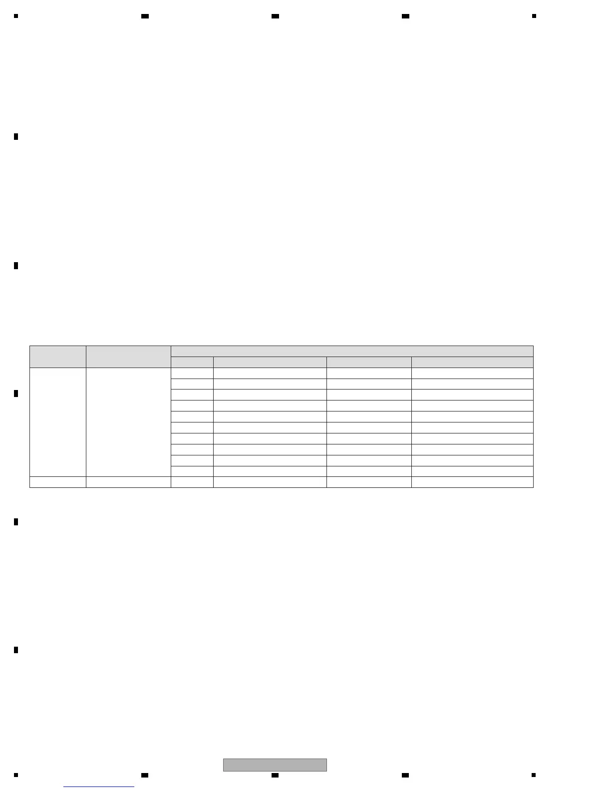
The part listed below is difficult to replace as a discrete component part.
When the part listed in the table is defective, replace whole Assy.
Assy Name PCB Assy Part No.
Parts that is Diffcult to Replace
Ref No. Function Part No. Remarks
MAIN Assy DWX3190
IC1406 12V → 1.2V DC/DC converter BD9326EFJ IC with heat-pad
IC1407 12V → 3.3V DC/DC converter BD9326EFJ IC with heat-pad
IC501 ETHER UCOM R5S76700B200BG BGA
IC1801 USB UCOM ADSP-BF524BBCZ-3A BGA
IC2214 FPGA XC3S50A-4FTG256C BGA
IC701 DSP D810K013BZKB400 BGA
Q3405 Transistor 2SD1760F5 (R) Transistor with heat-pad
Q3406 Transistor 2SB1184F5 (R) Transistor with heat-pad
Q3407 Transistor 2SD1760F5 (R) Transistor with heat-pad
Q3408 Transistor 2SB1184F5 (R) Transistor with heat-pad
CDCB Assy DWX3191 IC3601 CDC SENSOR AD7147ACPZ500RL7 IC with heat-pad
VOLTAGE MONITORING
This unit always monitors for power failure and will shut itself off immediately after an error is detected.
A power failure is indicated with flashing of the LFO FORM LED (Intervals: 250 ms [Lit 125 ms/Unlit 125 ms]).
All the LEDs other than LFO FORM will be unlit, and all the switches and VRs will be disabled.
Repair the unit according to the diagnostic procedures described in “5.4 Information on Power Diagnostics.”
CONFIRMATION OF USER-SETTING
This product has user- and club-setting data. Be sure to confirm those data before starting repair, although changing them
may not have a large effect. Use the Check Sheet in “8.5,” to which you can transcribe the settings, as required.
The settings are stored in Flash ROM (IC502) on the Main Assy.
To display the [USER SETUP] screen, hold [ON/OFF (UTILITY)] pressed for at least 1 sec.
To display the [CLUB SETUP] screen, press [POWER] (ON) while holding [ON/OFF (UTILITY)] pressed.
FLASH ROM ON THE MAIN Assy
Never replace the Flash ROM (IC502) on the MAIN Assy during servicing.
If the FLASH ROM is assumed to be defective, replace the whole MAIN Assy.
This FLASH ROM contains data that can only be written in at the factory.
An IEEE 802.3-based MAC address specific to this unit has been written.
 Loading...