A side
A side
D1204
1SS301
Q1203
(2/2)
3
5
4
HN 1A01FU(YGR)
Q1203
(1/2)
6
2
1
R1215
39k
(F)
R1219
1k
R1216
10k
R1217
3.3k
(D)
R1214
12k
(F)
R1218
12k
(D)
R1220
NM
V+9HP
V-9HP
V-9HP
V+5A
V+5A
STBY
A side
A Side
B side
B Side
!
!
100u/25
C1213
100u/25
C1206
47u/16
C1220
47u/16
C1221
NM
C1269
C1216
0.33u/50
C1271
1000p/50
CH
C1270
1000p/50
CH
C1218
0.1u/16
C1217
22u/16
CCG1254
C1219
1u/16
D1203
RB501V-40
D1202
RB501V-40
D1206
NM
D1205
NM
GN DA_HP
GN DA_HP
GN DA_HP
KIA7909PI
IC1202
1
GND
2
IN
3
OUT
KIA7809API
IC1201
1
IN
2
GND
3
OUT
CKF1089-A
KN1202
1
P1212
NM
12
P1211
NM
12
R1205
15
2W
R1229
0
R1228
0
R1206
15
2W
V+15A_HP
V+9HP
V-9HP
Drop Resister
HP Block
V+9HP
V-9HP
V+9HP_UNREG
V-9HP_UNREG
Drop Resister
STBY
STBY
STBY
STBY
STBY
A side
A side
D1204
1SS301
Q1203
(2/2)
3
5
4
HN 1A01FU(YGR)
Q1203
(1/2)
6
2
1
R1215
39k
(F)
R1219
1k
R1216
10k
R1217
3.3k
(D)
R1214
12k
(F)
R1218
12k
(D)
R1220
NM
V+9HP
V-9HP
V-9HP
V+5A
V+5A
STBY
A side
A Side
B side
B Side
!
!
47u/16
C1220
47u/16
C1221
NM
C1269
C1216
0.33u/50
C1271
1000p/50
CH
C1270
1000p/50
CH
C1218
0.1u/16
C1217
22u/16
CCG1254
C1219
1u/16
D1203
RB501V-40
D1202
RB501V-40
D1206
NM
D1205
NM
GN DA_HP
GN DA_HP
KIA7909PI
IC1202
1
GND
2
IN
3
OUT
KIA7809API
IC1201
1
IN
2
GND
3
OUT
P1212
NM
12
P1211
NM
12
R1205
15
2W
R1229
0
R1228
0
R1206
15
2W
V+9HP
V-9HP
Drop Resister
HP Block
V+9HP
V-9HP
V+9HP_UNREG
V-9HP_UNREG
Drop Resister
STBY
STBY
STBY
STBY
STBY
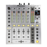
The voltage-monitoring circuits have been modified because of a malfunction found during mass-production of the products.
Note that the measures taken for the products may differ by the timing of the production.
• Malfunction: A shutdown may occur when certain headphones are used with this product.
• Cause: Malfunction of the voltage-monitoring circuits
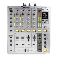
• Modifications: 1 Removal of the ±9-V monitoring circuit
2 Removal (short-circuiting) of the power-drop resistors (R1205, R1206)
1 ±9-V monitoring circuit 2 Power-drop resistors (R1205, R1206)
Timing of the production:
(1) All units with serial numbers beginning with KA or KB, and some units with serial
numbers beginning with KC or KD
(2) Some units with serial numbers beginning with KC, KD, or KF (planned), and all units
with serial numbers beginning with KE
(3) Some units with serial numbers beginning with KF, and all units with serial numbers
beginning with on and after KG (planned)
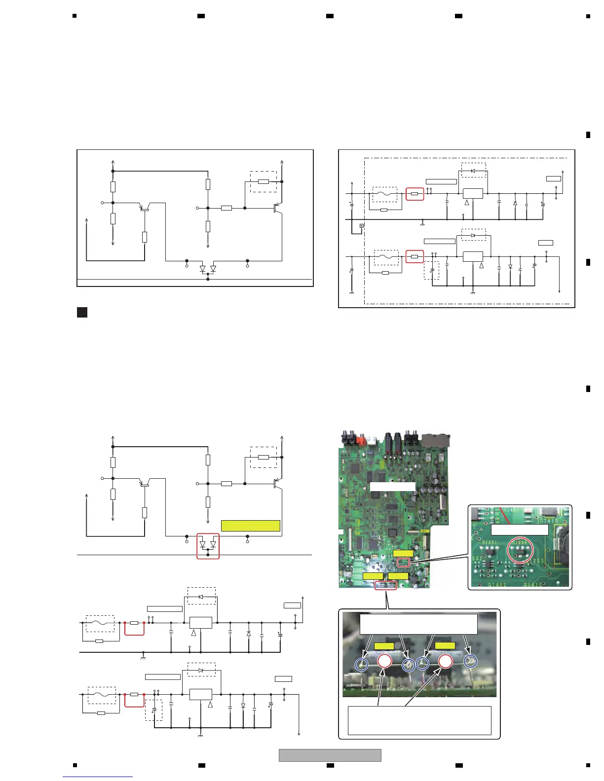
(1) All units with serial numbers beginning with KA or KB, and some units with serial numbers beginning with KC or KD
1 Removal of the chip diode [D1204].
2 Soldering of a lead wire or a piece of wire to R1205
and R1206.
Remove D1204.
D1204
R1206
R1206
R1205
R1205
Remove D1204.
MAIN ASSY
2. Securing the lead wires (pieces of wire) to
the resistors with adhesive
Silicone adhesive used: GYA1011
1. Soldering of a lead wire (or a piece
of wire) to the resistor

 Loading...