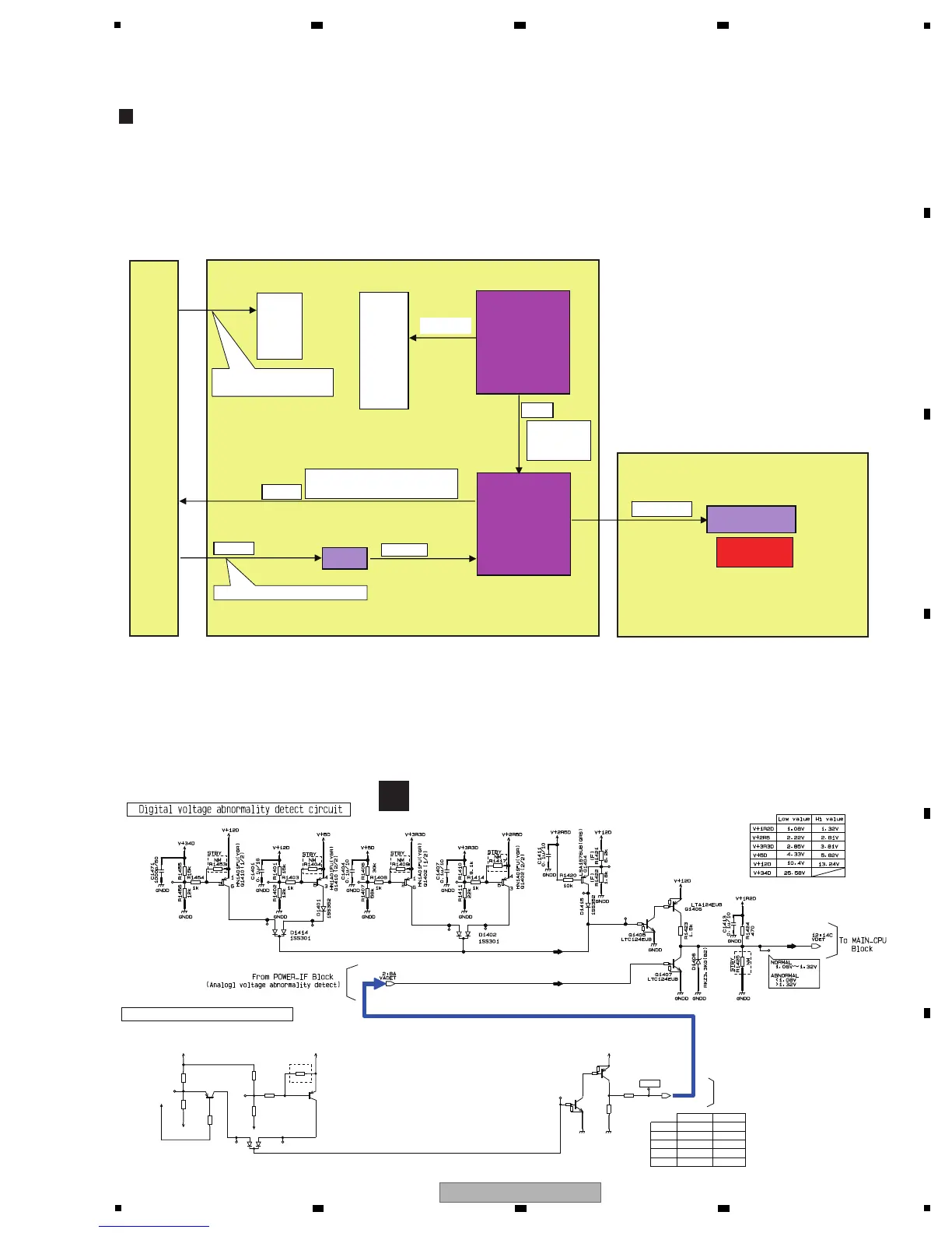
Voltage-Monitoring Circuit
This unit monitors the voltages of the main power-supply ICs, using the VDET signal.
The VDET signal level is middle (+1.08 V to +1.32 V) during normal operations. When the level becomes outside the middle
level, as shown in the table below, an error is informed to the MAIN CPU (IC2011).
Product behavior when an error is generated
Upon reception of the VDET signal that informs of power failure, the MAIN CPU sets the P-CON signal to Low and stops the
switching-system output from SW power.
The MAIN CPU also informs of power failure with flashing of the LFO FORM button, by sending the STBY_LED signal:
Flashing intervals: 250 ms (lit for 125 ms/unlit for 125 ms)
As the switching-system output is stopped, the indications other than the LFO FORM button are unlit and all the switches
and VRs are disabled.
Schematic diagram of the voltage monitoring section
MAIN ASSY
POWER SUPPLY ASSY
Voltage
monitoring
circuit
VMUTE
V+12D
V+15A
V-15A
V+5A
V+34D
V+12D
V+5D
V+3R3D
V+2R5D
V+1R2D
V+15A
V-15A
V+5A
The MAIN_CPU controls
power output.
Monitoring
VDET
H: Abnormal
Mid: Normal
L: Abnormal
IC1404
P-CON
H: SW power is output.
L: SW power output is stopped.
V+12E
V+3R3E
Always output during power-on
PNLA ASSY
STBY_LED
Flashing when
an error occurs
MAIN_CPU
(IC2011)
Analog voltage abnormality detect circuit
A side
A side
D1201
1SS301
GN DD
GN DD
LTC124EUB
Q1205
LTA124EUB
Q1206
HN 1A01FU(YGR)
Q1201
(2/2)
3
5
4
HN 1A01FU(YGR)
Q1201
(1/2)
6
2
1
R1207
10k
(F)
R1204
10k
R1209
1k
R1222
0
R1210
NM
R1208
22k
(F)
R1202
11k
(F)
R1221
10k
R1203
20k
(F)
VADET
V-15A_1
V-15A_1
V+15A_1
V+5A
V+5A V+12D
VADET
3:2C
To Power Block
STBY
V-15A
-11.82V
9.94V
-5.96V
16.74V
Low value
V+9HP
V-9HP
V+15A
4.28V 5.61V
8.23V
13.38V
Hi value
V+5A
-11.83V
-18.57V
LFO FORM LED
D6624 (RED)
G
MAIN ASSY

 Loading...