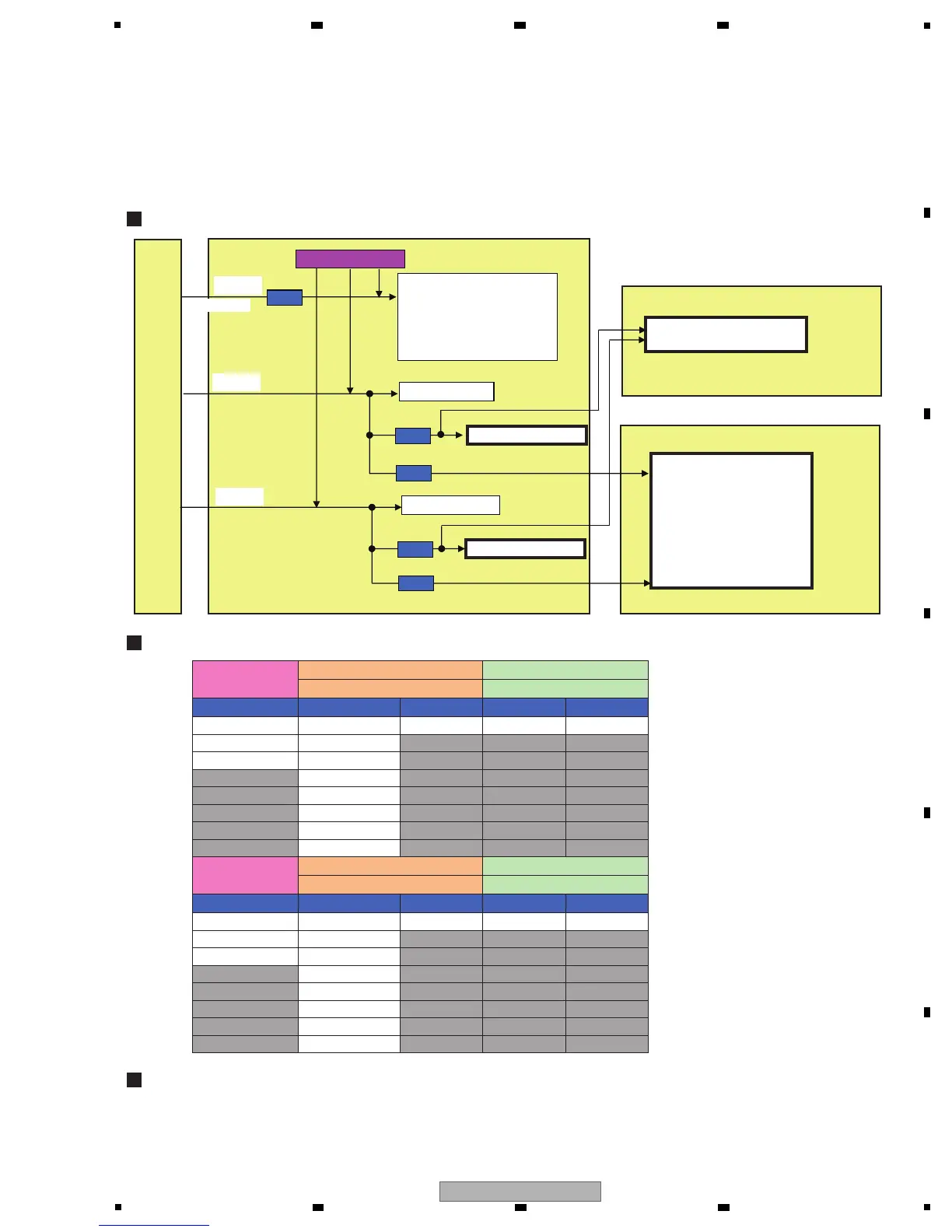
POWER SUPPLY ASSY
This unit monitors the voltages of the main power-supply ICs, using the voltage-monitoring circuit. As the ICPs (IC protectors)
are also used, some circuits cannot be monitored by the voltage-monitoring circuit when any wire for an ICP is broken.
(Circuits with thick frames in the figure below)
When any of the circuit blocks indicated in thick frames (located after the ICPs) in the figure below is in failure, also check for
a broken wire for the ICP.
1. Unplug the AC power cord.
2. Check for any error, such as short-circuiting or defective parts, in the circuits subsequent to the ICP.
3. Repair the detective part.
4. Replace the ICP.
INPUT ASSY
MAIN ASSY
ICP
Voltage monitoring
OUTPUT RELAY
INPUT RELAY
5V DC/DC converter
3.3V DC/DC converter
1.2V DC/DC converter
34V DC/DC converter
HP CIRCUIT *1
OUTPUT CIRCUIT *3
INPUT CIRCUIT *6
ICP
HP CIRCUIT *2
V+15A
V-15A
V+12D
non CIRCUIT
SEND ASSY
SEND CIRCUIT *5
ICP
ICP
ICP
P1204: DEK1103
P1210: DEK1095
P1207: DEK1121
P1209: DEK1096
P1208: DEK1121
Locations of the ICPs
Names of the Power-Supply ICs
Diagnostic procedures when the wire for an ICP is broken
OUTPUT CIRCUIT *4
Before the ICP *1
After the ICP (P1210) After the ICP (P1207)
OUTPUT BLOCK *3&5 INPUT BLOCK *6
MAIN MAIN SEND MAIN INPUT
V+15A_1
V+15A
V-15A
V+15A_O V+15A_SE V+15A_INV+15A_IN
V+15A_HP V+15A_SE
V+15A_HP_1 V+15A_SE_1
V+15A_BO
V+15A_M2
V+5A_REC
V+15A_M1
V+15A_M1_ICP
Before the ICP *2
After the ICP (P1209) After the ICP (P1208)
OUTPUT BLOCK *4&5 INPUT BLOCK *6
MAIN MAIN SEND MAIN INPUT
V-15A_1 V-15A_O V-15A_SE V-15A_INV-15A_IN
V-15A_HP V-15A_SE
V-15A_HP_1 V-15A_SE_1
V-15A_BO
V-15A_M2
V-5A_REC
V-15A_M1
V-15A_M1_ICP
 Loading...