FUEL SYSTEM/CARBURETION
4.11
5. Installthepilotmixturescrew,spring,washer ,and
O-ringasanassembly. Lubricatethe O-Ringwith
oil or light grease before installation. CAUTION:
Do not damage the O-ring during installation.
T urn the screw in until it lightly contacts the seat.
Back out the specified number of turns. NOTE:
Thefinalpilot (idle)mixture must be adjustedwith
the engine running. Refer to Page 2.12.
Pilot Mixture Screw Base Setting
(Set at Factory)
Refer to Specifications Page 1.4
FLOAT HEIGHT
ADJUSTMENT
1. Place the carburetor on a level surface as shown
at right to remove weight from float arm. In this
position, the float tongue will rest lightly on the
inlet needle valve pin without compressing the
spring.
Float Height:
Std: BST 40 14.7mm (.58″) ± 1mm
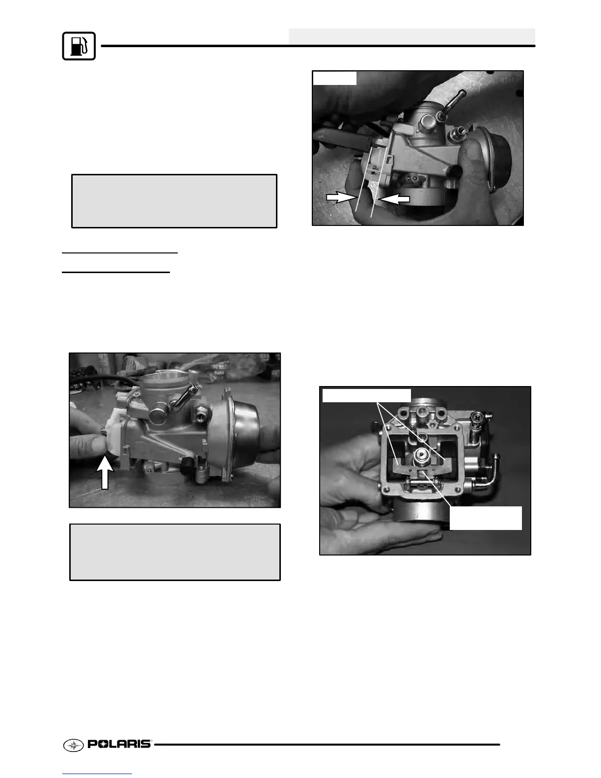
NOTE: On BST 40 carburetors, it is important to
press in on the float assembly as shown, to fully seat
the float assembly.
BST 40
2. Measure the height from the float bowl mating
surface to the top of step in float as shown. Both
sidesoffloatshouldbeparalleltoeachother. The
measurementshouldbemadeatthemid-pointon
the top of the float using Float Adjustment Tool
(PN 2872314) or a vernier caliper . When
measuring the height be sure the inlet needle
valve spring is not compressed.
3. If adjustment is necessary, bend the tongue
slightly. Besurefloatmeasurementisevenonleft
and right side.
Bend to adjust
float
Float arms even

 Loading...