MAINTENANCE
2.31
G Replace any worn steering
components. Steering should move
freely through entire range of travel
without binding.
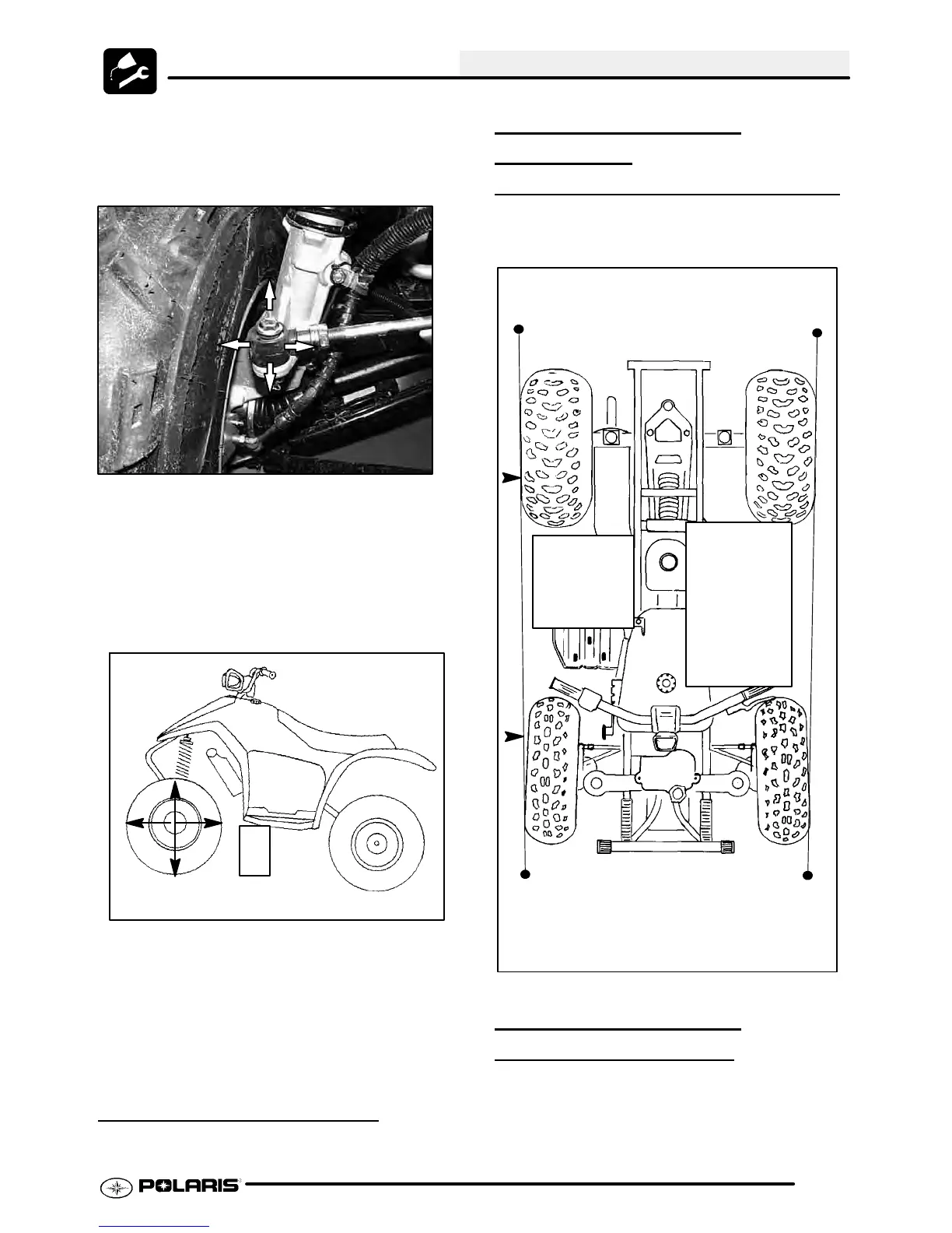
G Elevatefrontend of machine so front
wheels are off theground. Check for
any looseness in front hub / wheel
assembly by grasping the tire firmly
at top and bottom first, and then at
frontandrear. T rytomovethewheel
and hub by pushing inward and
pulling outward.
Check for Loose Wheel or Hub
G If abnormal movement is detected,
inspect the hub and wheel assembly
to determine the cause (loose wheel
nuts, loose front hub nut (4x4).
G Refer to the Body/Steering or Final
Drive chapter for more information.
CAMBER AND CASTER
The camber and caster are non-adjustable.
WHEEL ALIGNMENT
METHOD 1:
STRAIGHTEDGE OR STRING
Be sure to keep handlebars centered. See notes
below.
NOTE: String should just touch side sur-
face of rear tire on each side of machine.
NOTE: The steering post arm “frog” can be
used as an indicator of whether the handle-
bars are straight. The frog should always
point straight back from the steering post.
Rear rim
measure-
ment should
be 1/16″ to
1/8″ (.2to.3
cm) more
than front rim
measure-
ment.
Measure
from string
to rim at
front and
rear of rim.
WHEEL ALIGNMENT
METHOD 2:
CHALK
1. Place machine on a smooth level surface.
2. Set handlebars in a straight ahead position and
secure handlebars in this position. NOTE: The
steeringarm “frog” can be used as an indicator of
whether the handlebars are straight. The frog

 Loading...