ELECTRICAL
10.31
BRAKE LIGHT SWITCH
1. Disconnect wire harnessfromswitch. Locatedon
bulk head under front cover.
2. Connect an ohmmeter across switch contacts.
Reading should be infinite (∞).
3. Apply brake at handlebar lever and check for
continuity between switch contacts. Replace
switch if there is no continuity or greater than .5
ohms resistance when the brake is applied with
slight pressure.
HEADLAMP SWITCH
Head lamp connector
BRN
GRN
YEL
Probe the high beam Head lamp plug wires (Brown
and Yellow) at back of connector. Turn headlight
switch on. Test for battery voltage across the
connections.
NEUTRAL LIGHT CIRCUIT
OPERA
TION
Power is supplied to the transmission switch fromthe
Red/White wire when the key is on. When neutral is
selected, power flows through the switch to the
Green/Whitewire, throughthelampandto groundvia
the Brown wire.
Ifthelightis notonwhenneutralisselected,checkthe
bulb. If the bulb is good, check the wiring,
transmission switch, and lamp socket ground path.
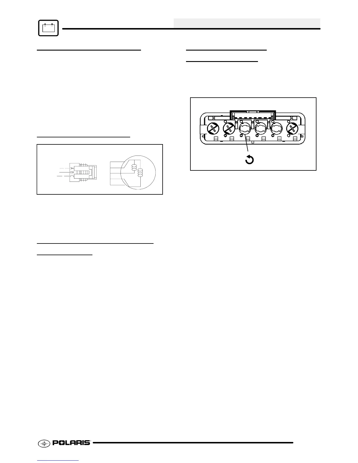
INDICATOR LAMP
REPLACEMENT
1. Remove retaining nuts holding choke and key
switch.
2. Disconnect indicator light panel from harness.
Rear view of indicator lamp panel
1/4 Turn
3. To remove defective light: Use a small
screwdriver and turn light holder a quarter turn
clockwise. Pulllight holder out witha needlenose
pliersor equivalent. Replacewithnew holder and
bulb assembly. Reassemble panel.

 Loading...