FINAL DRIVE
7.10
10. Using Roll Pin Remover (PN 2872608), remove
the roll pin at front housing.
Roller Pin Removal Tool (PN 2872608)
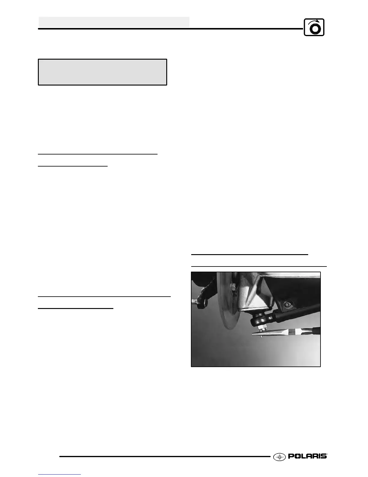
11. Remove the spindle and axle assembly from the
strut casting bearing by pulling the strut outward
as shown. Drive out the old seal, taking care not
to damage the tapered roller bearing. Install the
new seal until it bottoms against the shoulder in
the strut casting.
AWD FRONT DRIVE AXLE
INSTALLA
TION
1. Installspringwasheranddriveshaft. Alignholein
U-joint yoke with hole in eccentric shaft, and
install new roll pin.
2. Install new seal in strut casting. Refer to Page
7.14.
3. Install drive shaft in strut.
4. Installlowerballjoint,torquenutto 25ft. lbs.(34.5
Nm) and install new cotter pin.
5. Follow procedure to install hilliard clutch
components and hub as outlined in this chapter.
6. Tighten hub nut following procedures as outlined
in this chapter .
DRIVESHAFT AND CV JOINT
HANDLING
TIPS
S Care should be exercised during
driveshaft removal or when servicing CV
joints. Driveshaft components are
precision parts.
S Cleanliness and following these
instructions is very important to ensure
proper shaft function and a normal
service life.
S The complete driveshaft and joint should
be handled by getting hold of the
interconnecting shaft to avoid
disassembly or potential damage to the
driveshaft joints.
S Over-angling of joints beyond their
capacity could result in boot or joint
damage.
S Make sure surface-ground areas and
splines of shaft are protected during
handling to avoid damage.
S Do not allow boots to come into contact
with sharp edges or hot engine and
exhaust components.
S Thedriveshaftis not tobeusedasalever
arm to position other suspension
components.
S Never use a hammer or sharp tools to
remove or to install boot clamps.
S Be sure joints are thoroughly clean and
that the proper amount and type of
grease is used to refill when joint boots
are replaced and when joints are
cleaned. Refer to text for grease
capacity of CV joints and CV joint boots.
FRONT DRIVE SHAFT CV
JOINT BOOT
REPLACEMENT
1. Remove wheel, brake caliper and wheel hub.
Refer to front hub disassembly Page 7.3 for
procedure.

 Loading...